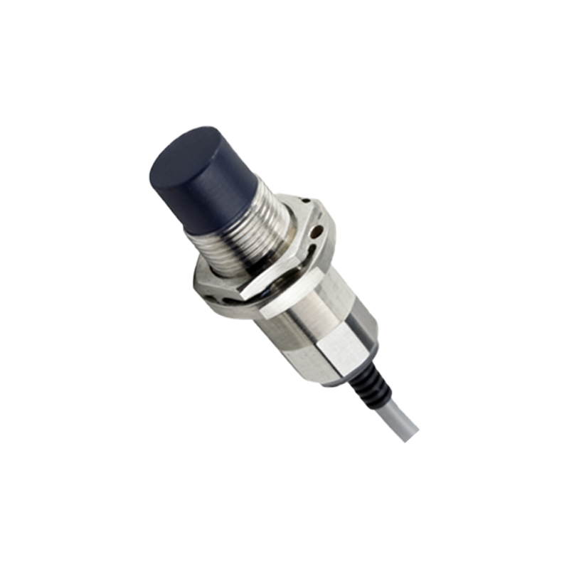
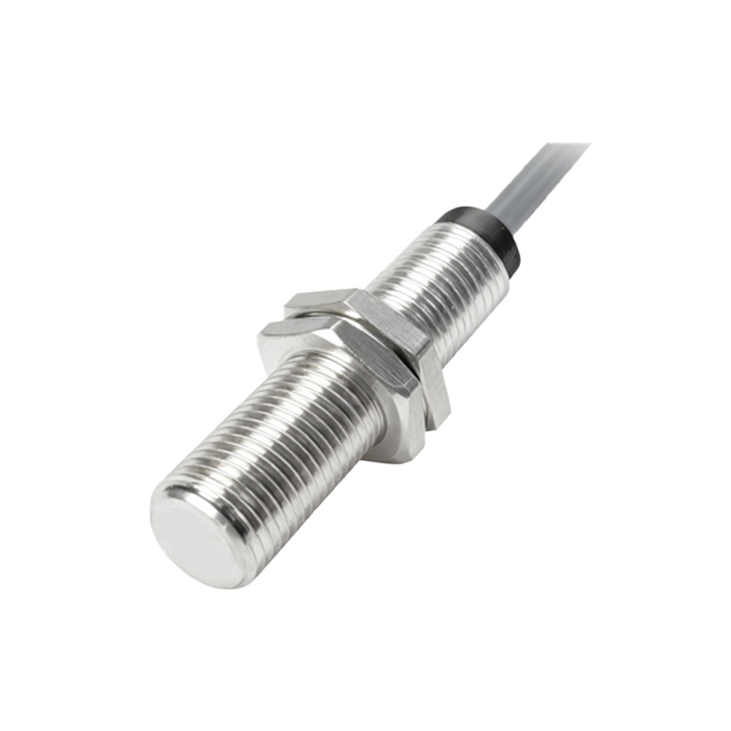
Infrared proximity sensors represent one of the most accessible and cost-effective solutions for non-contact object detection in modern electrical and automation systems. At their core, these devices operate on a straightforward principle: an infrared emitter, typically an IR LED, transmits a beam of invisible infrared light. When an object enters the sensor's detection range, this light is reflected back towards a receiver component, usually a phototransistor or photodiode tuned to the same IR wavelength. The receiver converts the reflected IR signal into an electrical output, which is then processed to indicate the presence or absence of the target.
The simplicity of this active infrared sensing method is its greatest strength. Unlike complex vision systems or high-precision laser sensors, a basic IR proximity sensor requires minimal supporting circuitry. A standard implementation might involve a current-limiting resistor for the emitter LED and a pull-up resistor for the phototransistor collector, forming a voltage divider network. The output voltage at the junction changes measurably when reflected IR light biases the phototransistor into conduction. This analog signal can be fed directly into a comparator for a digital on/off output or into a microcontroller's ADC pin for rudimentary distance estimation based on signal strength.
For engineers, selecting the right IR sensor begins with key parameters. Detection range, often between 2 cm to 30 cm for simple modules, must match the application. Response time is critical in high-speed automation; many basic sensors achieve response frequencies in the kilohertz range. The emitter's wavelength, commonly 850 nm or 950 nm, affects performance. The 950 nm variant is less susceptible to interference from ambient visible light. Environmental factors pose the main challenges. Sunlight, incandescent lamps, and other IR sources can cause false triggers. Simple countermeasures include modulating the emitted IR signal at a specific frequency (e.g., 38 kHz) and having the receiver circuit tuned to that same frequency, effectively filtering out constant ambient IR noise. Physical design considerations are equally important. The housing must separate the emitter and receiver to prevent internal crosstalk while allowing the reflected beam a clear path. The angle of emission and reception defines the sensor's field of view; a narrow beam is precise but requires alignment, while a wide beam is more forgiving but less accurate.
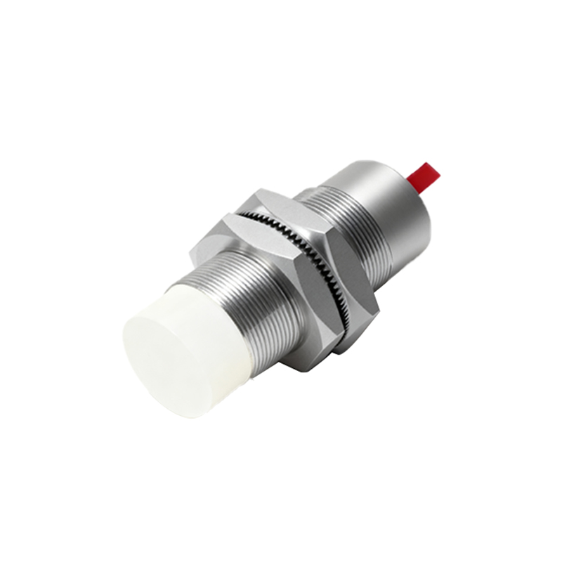
Typical applications abound in consumer electronics, industrial safety, and basic robotics. They serve as touchless switches in sanitary fixtures, paper detection in printers, obstacle avoidance in autonomous guided vehicles, and bin-level detection. Their low cost, small form factor, and ease of integration with digital logic or microcontrollers make them a default choice for proof-of-concept designs and high-volume products where extreme precision is not mandated.
In practice, implementing a reliable sensor involves calibration. The threshold for detection must be set considering the reflectivity of the target material—dark, non-reflective surfaces absorb IR light and drastically reduce effective range. Engineers often incorporate a potentiometer in the comparator reference circuit for field adjustment. For more stable performance across varying conditions, a closed-loop calibration routine run by a microcontroller can dynamically adjust the sensitivity. Despite their simplicity, these sensors are powerful tools. Their design embodies a key engineering philosophy: an elegant, minimal solution to a well-defined problem. By mastering their characteristics and limitations, engineers can deploy robust, maintenance-free detection in countless scenarios, forming the sensory foundation for more complex automated systems.