In modern industrial automation and precision measurement systems, laser distance sensors have become indispensable tools. Their ability to provide non-contact, high-accuracy, and rapid distance measurements makes them critical for applications ranging from robotics and logistics to quality control and safety systems. However, achieving the specified accuracy and reliability is not solely dependent on the sensor's inherent specifications. A crucial, yet often underestimated, factor is the sensor's orientation relative to the target surface. Incorrect orientation can lead to significant measurement errors, signal loss, or even sensor damage. This article delves into the principles of optimal laser sensor orientation, its impact on performance, and practical guidelines for installation.
The core working principle of most industrial laser distance sensors is based on either time-of-flight (ToF) or triangulation. In both methods, a laser diode emits a focused beam of light towards a target. The sensor then detects the reflected light. For ToF sensors, it calculates distance by measuring the time delay between emission and reception. For triangulation sensors, the position of the reflected spot on a receiver (like a CCD or PSD array) changes with distance. The orientation of the sensor directly affects how this beam strikes the target and how the reflection is captured.
The primary consideration is the angle of incidence—the angle between the incoming laser beam and a line perpendicular (normal) to the target surface. The ideal condition is for the laser beam to be incident perpendicularly (0° angle of incidence). In this scenario, the maximum amount of reflected light travels directly back along the same path to the sensor's receiver, ensuring a strong and unambiguous signal. When the sensor is tilted, creating a non-perpendicular angle, several issues arise.
First, the effective measurement point shifts. This is a geometric error. If you measure a distance to a tilted surface with a non-perpendicular beam, the reported distance is to the point where the beam hits, not necessarily the point directly in front of the sensor's mechanical housing. This must be accounted for in system calibration. Second, and more critically, the signal strength diminishes. A non-perpendicular incidence causes the laser spot to elongate into an ellipse, reducing its intensity per unit area. Furthermore, the reflection becomes specular (mirror-like) rather than diffuse. Instead of scattering light in all directions, a specular surface reflects the beam at an angle equal to the angle of incidence. If this reflection angle does not align with the receiver's aperture, the sensor may receive little to no signal, resulting in a measurement dropout.
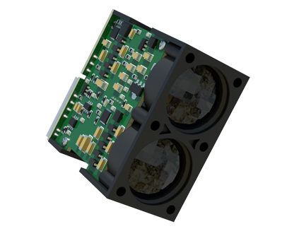
The nature of the target surface is intrinsically linked to orientation requirements. For optimal performance with diffuse surfaces (e.g., matte white paint, rough concrete, most untreated materials), a small deviation from perpendicular (typically up to 5-10 degrees) is often tolerable because the surface scatters light sufficiently. However, for specular or highly reflective surfaces (e.g., polished metal, glass, glossy plastic), the orientation must be meticulously controlled. A common technique for measuring such surfaces is to deliberately set the sensor at a stable, fixed angle to avoid direct retro-reflection, which can oversaturate the receiver, and instead capture the diffuse component from surface imperfections. Alternatively, applying a diffuse marker (like tape or special spray) to the measurement point can solve the issue.
Environmental factors also interact with orientation. Ambient light, especially direct sunlight or strong artificial light from specific directions, can interfere with the sensor's receiver. Orienting the sensor so that its optical axis is not pointing towards a major light source can mitigate this. Similarly, in environments with dust, steam, or oil mist, orienting the sensor vertically (beam pointing downwards) can help prevent the accumulation of contaminants on the lens, compared to a horizontal orientation where settling is more likely.
Practical installation guidelines are straightforward but vital. Always consult the sensor's datasheet for its specified allowable tilt angle. Use high-quality, rigid mounting brackets to prevent vibration or thermal drift from altering the set orientation. During commissioning, verify the measurement at the intended working distance and angle on the actual target material. For dynamic applications where the target angle changes, such as on a conveyor with uneven objects, selecting a sensor with a wider acceptance angle or using multiple sensors may be necessary.
In robotics, for example, a laser sensor on a gripper must be oriented to measure the distance to a part reliably regardless of the part's slight positional variances. In roll diameter measurement in paper or steel mills, the sensor must be precisely angled to avoid the highly specular surface of the material. In vehicle alignment systems, sensors must be perpendicular to the measurement planes to ensure geometric accuracy.
In conclusion, the orientation of a laser distance sensor is a fundamental parameter for system integration, as critical as choosing the right measurement range or output type. By understanding the interplay between beam angle, surface properties, and environmental conditions, engineers can deploy these powerful sensors to achieve consistent, high-precision results. Neglecting this aspect can turn a high-accuracy sensor into a source of unreliable data, while careful attention to orientation ensures robust performance and maximizes return on investment in automation projects.