In the realm of industrial automation and control systems, ultrasonic proximity sensors have emerged as a pivotal technology for non-contact detection and measurement. These sensors operate on the principle of emitting high-frequency sound waves and analyzing the reflected signals to determine the presence, distance, or position of objects. The schematic diagram of an ultrasonic proximity sensor provides a detailed visual representation of its internal components and their interconnections, offering engineers and technicians a roadmap for design, troubleshooting, and optimization.
At the core of the schematic, one typically finds the ultrasonic transducer, which serves as both the transmitter and receiver. This piezoelectric element converts electrical energy into ultrasonic waves (usually in the range of 20 kHz to 200 kHz) and vice versa. The transducer is driven by an oscillator circuit that generates the required frequency pulses. In the schematic, this is often depicted as a square wave generator connected to a power amplifier, which boosts the signal to ensure sufficient energy for emission. The timing of these pulses is critical, as it dictates the sensor's resolution and range capabilities.
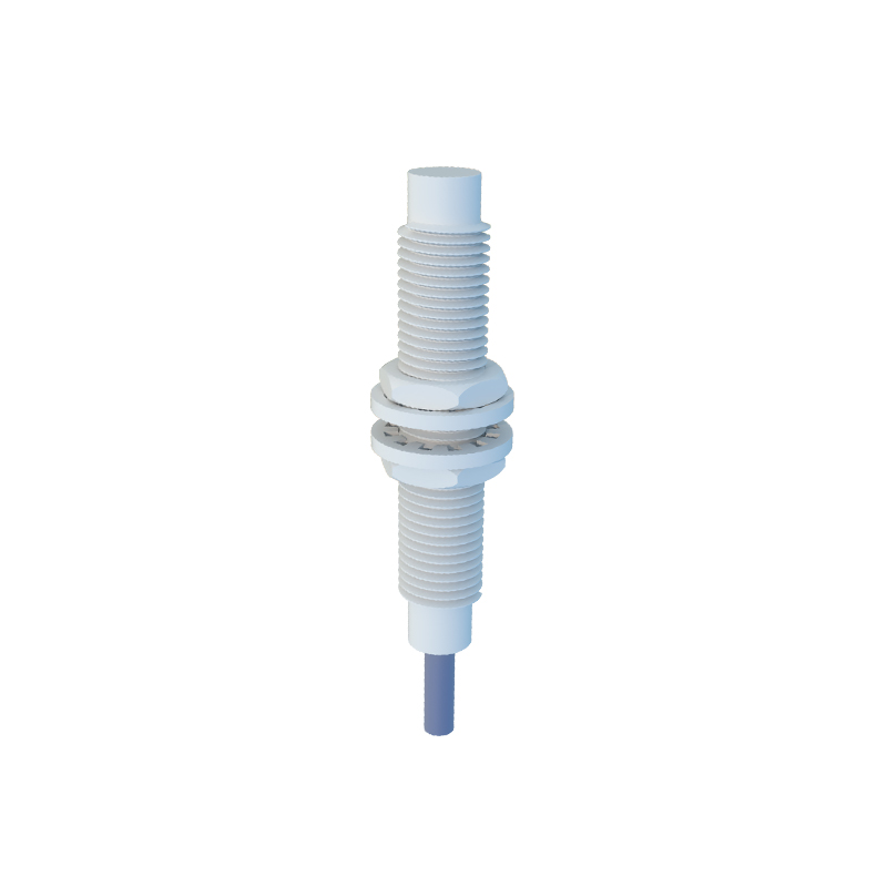
Adjacent to the transmitter section, the receiver circuit is illustrated, comprising an amplifier, filter, and comparator. When the ultrasonic waves encounter an object, they reflect back to the transducer, which then converts them into weak electrical signals. These signals are first amplified by a low-noise amplifier to enhance their strength. Following this, a band-pass filter eliminates noise and interference from other frequencies, ensuring that only the relevant echo signals are processed. The comparator circuit then evaluates the amplified and filtered signal against a threshold voltage to detect the presence of an echo, thereby indicating an object's proximity.
The control logic unit, often represented by a microcontroller or dedicated integrated circuit (IC) in the schematic, plays a crucial role in coordinating the sensor's operations. It manages the timing between transmission and reception, calculates the time-of-flight (ToF) of the sound waves, and converts this data into distance measurements using the formula: distance = (speed of sound × time) / 2. The speed of sound is typically adjusted for environmental factors like temperature and humidity, with compensation circuits sometimes included in the schematic for accuracy. This unit also interfaces with output stages, such as analog voltage/current outputs or digital signals (e.g., PNP/NPN transistors), which communicate the detection results to external systems like PLCs or HMIs.
Power supply sections in the schematic highlight the need for stable voltage regulation, as ultrasonic sensors are sensitive to fluctuations. Common configurations include linear regulators or switching converters that provide clean DC power to the analog and digital components. Protection circuits, such as overvoltage clamps and reverse-polarity diodes, are also integrated to safeguard against electrical faults in harsh industrial environments. Additionally, some schematics feature calibration potentiometers or digital trimming elements, allowing for fine-tuning of sensitivity and response thresholds during installation.
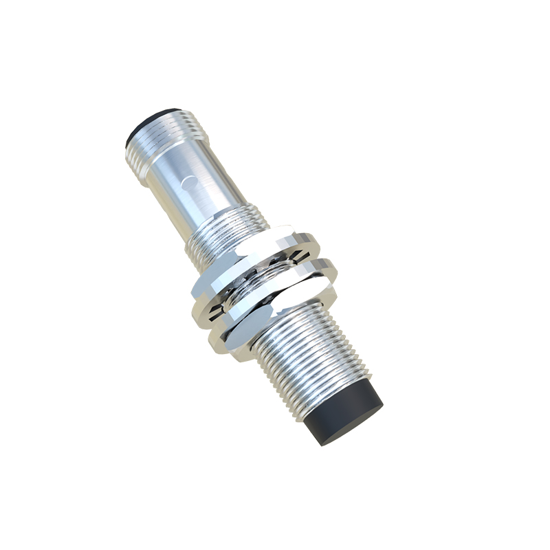
Understanding the schematic diagram enables professionals to appreciate the sensor's limitations and advantages. For instance, the diagram reveals how factors like beam angle and material composition affect performance—soft or absorbent materials may weaken echoes, while angled surfaces can deflect signals. By analyzing the interconnections, one can diagnose issues like signal attenuation or false triggers, often traced to faulty amplifiers or misaligned transducers. Moreover, the schematic aids in customizing sensors for specific applications, such as liquid level sensing or object counting, by modifying component values or adding supplementary circuits.
In summary, the schematic diagram of an ultrasonic proximity sensor is more than just a technical drawing; it is a comprehensive guide that elucidates the synergy between electronic components to achieve reliable non-contact detection. Mastery of this diagram empowers engineers to innovate, maintain, and deploy these sensors effectively across diverse industries, from automotive manufacturing to robotics, ensuring precision and efficiency in automated processes.