In the demanding world of construction and concrete placement, the concrete pump truck stands as a critical piece of equipment. A key component ensuring its precise and safe operation is the proximity sensor. These sensors, often inductive or capacitive, are tasked with detecting the position of the boom, outriggers, or the state of hydraulic cylinders without physical contact. However, a persistent and costly issue plagues many fleet managers and maintenance crews: the frequent failure of these proximity sensors. This recurring problem leads to unexpected downtime, safety concerns, and increased operational costs. Understanding the root causes is the first step toward implementing lasting solutions.
The operating environment for a pump truck proximity sensor is exceptionally harsh, which is the primary contributor to its premature failure. Sensors are constantly exposed to a combination of damaging elements. Concrete slurry and dust are highly abrasive and can infiltrate sensor housings, damaging internal components and coating the sensing face, which attenuates the signal. Water and hydraulic fluid are ever-present threats; despite claims of high IP ratings, prolonged exposure or damaged seals can lead to internal short circuits or corrosion of electrical connections. Furthermore, the sensor and its wiring are subject to extreme mechanical stress. Vibration from the diesel engine and hydraulic system can loosen mounting brackets, fracture solder joints inside the sensor, or cause wire fatigue at connection points. Physical impact from debris, tools, or during transport is also a common cause of housing damage or misalignment.
Electrical issues represent another major failure category. Voltage spikes and surges in the truck's electrical system, often generated by solenoids, relays, or the alternator, can easily overwhelm the sensor's internal electronics. Inadequate or unstable power supply, sometimes due to poor battery connections or faulty voltage regulators, forces the sensor to operate outside its specified range, leading to erratic behavior or thermal damage. Grounding problems are notoriously difficult to diagnose. A poor chassis ground can create ground loops or reference voltage shifts, causing the sensor to provide false signals or none at all. The integrity of the cable and connector is equally vulnerable; pinched wires, corroded pins, or connectors not fully seated expose the system to moisture and lead to intermittent failures.
Improper selection, installation, and maintenance practices often set the stage for failure. A sensor chosen with an insufficient sensing range for the application may be physically struck by the target. Using a standard industrial sensor instead of one designed for heavy-duty mobile equipment (with enhanced vibration and shock resistance) is a common mistake. During installation, incorrect mounting, such as over-tightening or using incompatible brackets, can distort the sensor housing. Incorrect alignment with the target metal (for inductive sensors) drastically reduces effective sensing distance. A lack of routine maintenance allows the aforementioned environmental factors to take their toll unchecked. Sensors caked in concrete are rarely cleaned, and wiring is seldom inspected for chafing or loose connections.
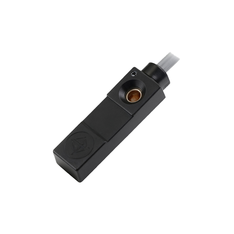
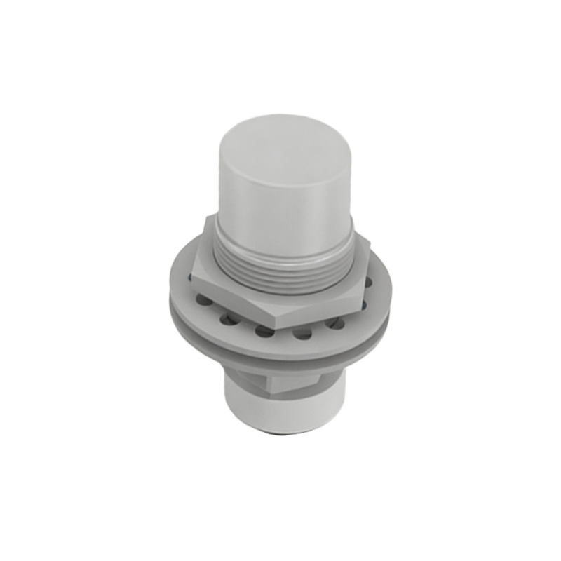
To combat these failures, a proactive, systematic approach is required. Begin with sensor selection: insist on sensors specifically engineered for mobile hydraulic applications. Look for robust housings (often stainless steel), high IP (Ingress Protection) and IK (Impact Protection) ratings, and extended temperature ranges. M12 or M18 form factors with ruggedized, PUR-jacketed cables are typically a good choice. During installation, follow the manufacturer's specifications meticulously. Ensure secure mounting using proper hardware and anti-vibration solutions if needed. Verify precise alignment and maintain the recommended sensing gap. Protect wiring with conduit or spiral wrap, especially in high-flex or abrasion-prone areas, and secure cables with clamps to prevent strain on the connector.
Implementing a rigorous preventive maintenance schedule is non-negotiable. During daily or weekly walk-arounds, visually inspect all sensors for physical damage, accumulation of material, and security of mounting. Clean the sensing face regularly with appropriate solvents. Periodically, use a multimeter to check supply voltage at the sensor connector and verify switching signals. Inspect the entire wire harness for damage. From an electrical system perspective, consider installing protective devices like transient voltage suppressors (TVS diodes) or zener barriers on sensitive sensor lines to clamp voltage spikes. Ensure the vehicle's charging system is functioning correctly and that all ground connections to the chassis are clean, tight, and free of paint.
Ultimately, while the pump truck environment will always be challenging, understanding the multifaceted reasons for proximity sensor failure—environmental assault, electrical stress, and human factors—enables a shift from reactive replacement to proactive management. By investing in the right sensors, installing them correctly, and adhering to disciplined maintenance, equipment managers can significantly enhance sensor reliability, reduce costly downtime, and ensure the safe, continuous operation of their concrete pump trucks.