Laser displacement sensors are non-contact measurement devices that have become indispensable in modern industrial automation, quality control, and research. An experiment to understand and utilize these sensors provides invaluable insight into their operation, capabilities, and limitations. This article details a fundamental laser displacement sensor experiment, explaining the core principles, a typical setup procedure, key measurement parameters, and analysis of results.
The fundamental principle behind a laser displacement sensor is triangulation. The sensor's emitter projects a focused laser spot onto the target surface. The reflected light from this spot is then received by a position-sensitive detector (PSD) or a CMOS/CCD element within the sensor. When the target's distance changes, the angle of the reflected light shifts, causing the position of the light spot on the detector to move. The sensor's internal processor calculates the displacement by analyzing this positional change on the detector. This method allows for high-speed, high-precision measurements without physical contact, preventing damage to both the sensor and the target.
Setting up a laser displacement sensor experiment requires careful consideration of several components. The primary equipment includes the laser displacement sensor itself (commonly with a red or blue laser), a stable mounting system like an optical breadboard or a rigid stand, a precision translation stage to move the target in a controlled manner, a variety of target samples with different surface properties (e.g., matte white metal, polished steel, dark plastic, translucent materials), and a data acquisition system. This system could be the sensor's dedicated controller/amplifier connected to a computer via USB or Ethernet, or a data logger. The sensor must be securely mounted perpendicular to the primary direction of expected target movement to minimize cosine error. The connection between the sensor, its controller, and the PC running the measurement software is then established.
Before taking measurements, critical parameters must be configured in the sensor's software. The measurement range, which is the distance over which the sensor can operate within its specified accuracy, must be selected. The sampling rate, or how many measurements per second the sensor takes, should be set appropriately for the application; a high rate is needed for vibrating objects, while a lower rate suffices for slow movements. Filter settings, such as moving average or low-pass filters, help to smooth out electrical noise from the output signal. Finally, the sensor must be calibrated. This often involves a simple two-point calibration using the translation stage: place the target at a known reference distance (zero point) and set the output, then move it a precise known distance (span point) and adjust the scale.
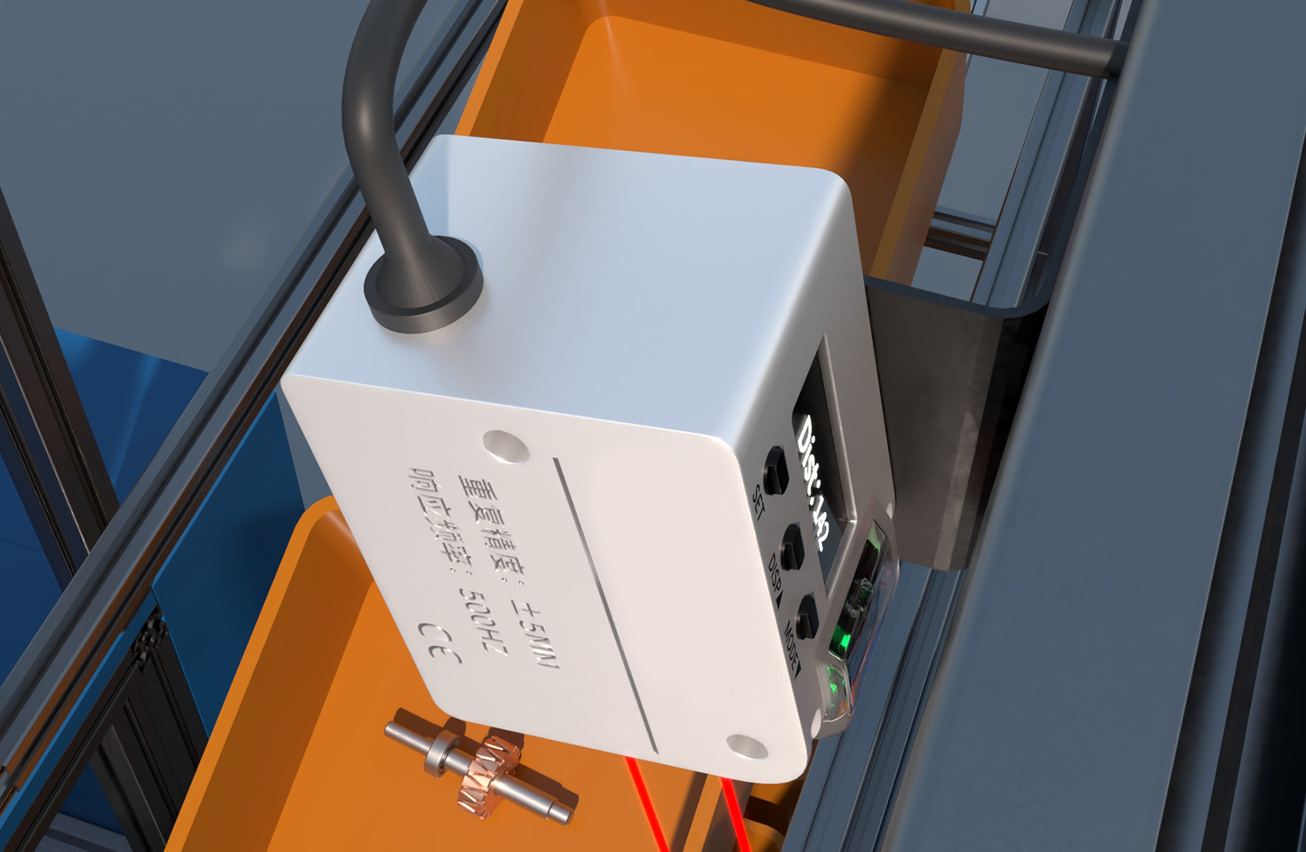
The experimental procedure begins with a static measurement test. A flat, matte white target is placed within the sensor's measurement range. Using the translation stage, the target is moved in precise increments (e.g., 0.1 mm or 0.01 inch) across the range. At each position, the sensor's output is recorded. This data is then plotted as Sensor Output versus Actual Displacement (from the translation stage's micrometer). The resulting graph reveals the sensor's linearity—how perfectly straight the response line is. The deviation from a perfect straight line is the linearity error, a key specification. Next, repeatability is tested by moving the target to the same position multiple times and recording the variation in readings.
A crucial part of the experiment involves testing the sensor's performance with different target surfaces. The matte white surface typically yields the best results due to its ideal, diffuse reflection. Switching to a shiny, specular surface like polished metal can cause significant errors or signal loss if the reflected beam misses the detector. Dark or black surfaces absorb more light, potentially reducing signal strength and increasing noise. Translucent materials (e.g., glass, clear plastic) allow the laser to penetrate, often giving a false reading from an internal surface or the rear wall. These tests highlight the importance of surface condition in practical applications and may necessitate sensor adjustments or the use of specialized models.
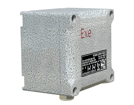
Dynamic measurements can also be explored. By attaching the target to a small vibrating source or a motor-driven cam, the sensor can capture oscillatory motion. The high sampling rate enables the analysis of vibration amplitude and frequency. This demonstrates the sensor's capability for real-time monitoring of moving parts.
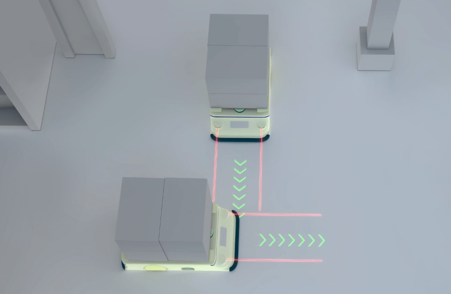
Analyzing the data involves calculating key performance metrics. Resolution, the smallest detectable change, is observed from the noise level in static readings. Accuracy is a combination of linearity error, temperature drift, and other factors, assessed by comparing the average measured value to the known standard at various points. The experiment's findings directly correlate to real-world applications. In automotive manufacturing, such sensors measure panel gap dimensions. In electronics, they verify component coplanarity. In laboratory research, they monitor material deformation under stress.
In conclusion, a hands-on laser displacement sensor experiment effectively bridges theoretical knowledge and practical application. It reinforces understanding of optical triangulation, highlights the critical influence of setup parameters and target surface properties, and provides a clear methodology for evaluating sensor performance specifications like linearity, repeatability, and resolution. This foundational knowledge is essential for anyone seeking to implement precise, non-contact measurement solutions in industrial or scientific settings.