Proximity sensors are indispensable components in modern industrial automation, robotics, and safety systems. Their ability to detect the presence or absence of an object without physical contact ensures reliability, longevity, and precision. However, the performance and longevity of these devices are heavily dependent on correct installation. A poorly installed sensor can lead to false triggers, reduced sensing range, premature failure, and costly downtime. This guide outlines the critical steps and considerations for a successful proximity sensor installation, ensuring you get the most out of your investment.
The installation process begins long before mounting the sensor. The first and most crucial step is selecting the right sensor for the application. Key parameters include the sensing distance, target material, environmental conditions, output type (e.g., NPN, PNP, analog), and housing style (e.g., cylindrical, rectangular, ring-shaped). Inductive sensors detect metals, while capacitive sensors can detect both metallic and non-metallic materials. Ultrasonic and photoelectric sensors offer longer ranges for diverse materials. Always consult the sensor's datasheet for its nominal sensing distance (Sn) and ensure the actual installation provides a 10-20% margin. Never operate the sensor at its absolute maximum rated distance.
Once the correct sensor is selected, careful planning of the mounting location is essential. The sensor must be positioned so that the target approaches the sensing face correctly. For cylindrical inductive sensors, the standard sensing direction is axially towards the front face. Consider the target's size, shape, and approach angle. The target should be large enough and made of the specified material to ensure reliable detection. Avoid mounting sensors where they will be exposed to direct physical impact, excessive vibration, or where chips, coolants, or dirt might accumulate directly on the sensing face. Environmental factors are paramount; for harsh environments involving washdowns, oils, or chemicals, specify sensors with appropriate IP (Ingress Protection) ratings, such as IP67 or IP69K.
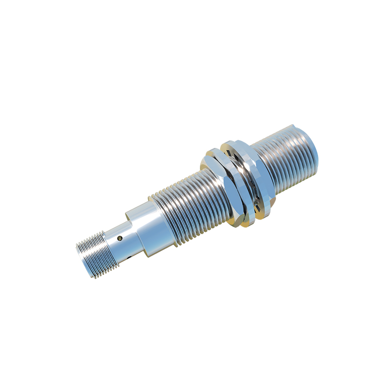
Mechanical mounting requires precision. For threaded barrel sensors, use the correct size locknut and ensure it is tightened to the specified torque. Overtightening can damage the housing or threads, while undertightening can lead to movement and misalignment. The sensor must be securely fixed; any vibration or movement will compromise accuracy. Maintain the recommended clearance around the sensor body. Most inductive sensors require a metal-free zone around their sides to prevent interference from the mounting bracket itself. Typically, a clearance of one to two times the sensor's diameter is necessary. Flush-mountable sensors are designed to be installed flush with a metal surface, while non-flush sensors require this clearance for proper operation.
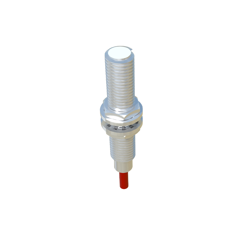
Electrical wiring is the next critical phase. Always disconnect power before making any connections. Follow the wiring diagram provided in the sensor's manual meticulously. Incorrect wiring is a leading cause of sensor failure. Key connections include the power supply (V+ and V- or 0V), the load (often a PLC input, relay, or indicator), and the output wire. Pay close attention to the sensor's output configuration (sourcing/NPN or sinking/PNP) and ensure it is compatible with your controller's input circuit. Use shielded cables in electrically noisy environments, such as those near variable frequency drives (VFDs) or welding equipment, and ground the shield at one end only to prevent ground loops. Keep sensor cables away from power lines to minimize electromagnetic interference. Secure cables with cable ties, avoiding sharp bends that could damage internal conductors.
After mechanical and electrical installation, thorough testing and adjustment are mandatory. Apply power and use the target object to test the sensor's response. Verify the sensing distance under real operating conditions. Many sensors feature a built-in LED indicator that lights up when an object is detected—this is an invaluable diagnostic tool. Fine-tune the sensor's position if necessary. For adjustable sensors, some may have a potentiometer for sensitivity adjustment. Use this to compensate for minor variations in target material or to ignore background objects, but avoid setting the sensitivity so high that it causes instability.
Finally, implement a routine inspection and maintenance schedule. Periodically check the sensor for physical damage, cleanliness, and secure mounting. Clean the sensing face with a soft cloth to remove oil, dust, or debris that could attenuate the signal. Check electrical connections for corrosion or looseness. Documenting the installation details, including sensor model, location, and date, aids in future troubleshooting and replacement.
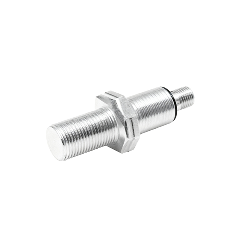
In conclusion, proper proximity sensor installation is a systematic process involving correct selection, careful mechanical mounting, accurate electrical wiring, and diligent testing. By adhering to these guidelines, you ensure reliable object detection, maximize sensor lifespan, and maintain the efficiency and safety of your automated systems. A little extra time spent on correct installation prevents significant losses in productivity and cost down the line.