Proximity sensors are fundamental components in modern industrial automation, providing non-contact detection of objects. Understanding their working principle is crucial for engineers and technicians involved in system design, maintenance, and troubleshooting. This article delves into the core operational principles of various proximity sensor types, supported by high-definition images to illustrate key concepts clearly.
The primary function of a proximity sensor is to detect the presence or absence of an object within its sensing range without physical contact. This is achieved through the emission of an electromagnetic field, beam of light, or sound waves. The sensor's internal circuitry monitors changes in this emitted signal caused by a target object. The most common types include inductive, capacitive, ultrasonic, and photoelectric sensors.
Inductive proximity sensors are widely used for detecting metallic objects. The core principle involves an oscillator circuit that generates a high-frequency electromagnetic field at the active face of the sensor. When a conductive metal target enters this field, eddy currents are induced on the target's surface. These eddy currents draw energy from the oscillator, causing a reduction in its amplitude. This amplitude change is detected by a threshold circuit, which subsequently switches the sensor's output state. High-definition images of inductive sensors clearly show the coil windings and ferrite core responsible for generating the field, as well as the damping effect caused by different metals.
Capacitive proximity sensors can detect both metallic and non-metallic materials, such as liquids, plastics, or wood. They operate based on the principle of capacitance change. The sensor face acts as one plate of a capacitor, with the target object acting as the other plate, and the air gap as the dielectric. An internal oscillator is tuned to a specific frequency. When a target enters the sensing zone, it alters the dielectric constant and thus the capacitance of the system. This change in capacitance affects the oscillator's amplitude or frequency, triggering the output switch. Detailed diagrams illustrate the electrostatic field lines and how different materials with varying dielectric constants influence the sensing distance.
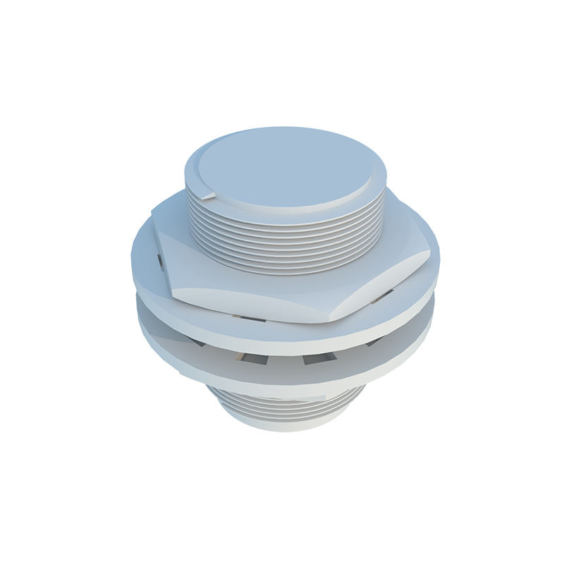
Ultrasonic proximity sensors utilize sound waves beyond the human hearing range. They contain a transducer that emits high-frequency ultrasonic pulses (typically 40-200 kHz) and then listens for the echo reflected from a target object. The sensor measures the time interval between the emitted pulse and the received echo. This time-of-flight measurement is directly proportional to the distance to the target. Cross-sectional images reveal the piezoelectric crystal responsible for generating and receiving the sound waves, and the timing diagrams explain the crucial echo processing logic for accurate detection, even for sound-absorbing materials.
Photoelectric sensors use light, often infrared or laser, for detection. The basic principle involves an emitter that projects a light beam and a receiver that detects it. In the through-beam (opposed) mode, detection occurs when an object interrupts the beam between separate emitter and receiver units. In the retro-reflective mode, the emitter and receiver are housed together, and a reflector bounces the light back; an object is detected when it blocks this reflected beam. The diffuse (proximity) mode relies on the target object itself reflecting the emitted light back to the co-located receiver. High-resolution images are invaluable for showing the light path, lens configurations, and the difference between modulated light signals and ambient light interference.
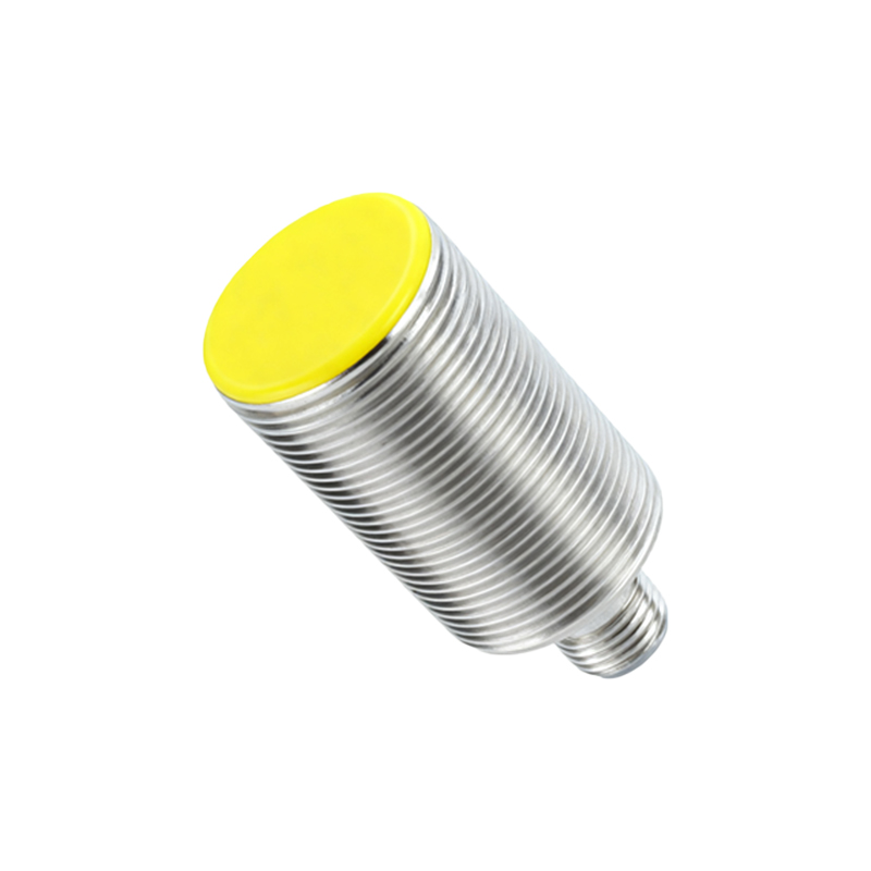
The output stage of a proximity sensor is typically a solid-state switch (PNP or NPN for DC sensors) or a relay contact. The switching logic (normally open or normally closed) is defined by the application's safety and control requirements. Internal schematic diagrams in high definition help engineers understand the signal flow from the sensing element through amplification and conditioning circuits to the final output driver.
Selecting the right sensor requires careful consideration of factors like sensing distance, target material, environmental conditions (temperature, humidity, contaminants), and output type. Mounting considerations, such as flush or non-flush installation for inductive sensors, significantly affect the nominal sensing range, as shown in comparative installation diagrams.
In conclusion, a clear grasp of proximity sensor principles, aided by detailed, high-quality images, empowers engineers to design more robust, efficient, and reliable automated systems. From the electromagnetic fields of inductive sensors to the time-of-flight calculations in ultrasonic models, each technology offers unique advantages for specific industrial challenges. Proper selection and application hinge on this fundamental understanding.