In industrial automation and control systems, proximity sensors are indispensable components for non-contact detection of metallic or non-metallic objects. Their reliability is critical for process continuity, safety, and efficiency. However, a common and frustrating issue encountered by electrical and maintenance engineers is a proximity sensor showing no response. This failure can halt production lines, cause safety hazards, and lead to costly downtime. Understanding the root causes requires a systematic approach, moving from basic power checks to more complex environmental and application-specific factors.
The first and most fundamental step in troubleshooting is verifying the power supply. A sensor with no reaction often points to a complete lack of operational voltage. Begin by checking if the correct voltage (e.g., 10-30V DC for most models) is present at the sensor's supply terminals using a multimeter. Ensure the polarity is correct for DC sensors; reversing positive and negative leads will prevent operation. Inspect the wiring for loose connections, broken wires, or poor terminations. Don't overlook the fuse or circuit breaker supplying the circuit—it may have tripped. For sensors integrated into a Programmable Logic Controller (PLC) system, verify the corresponding input module's health and its indicator lights.
Assuming power is confirmed, the next area of investigation is the sensor's sensing range and the target object. Every proximity sensor has a specified nominal sensing distance (Sn). A lack of response frequently occurs because the target is simply out of this range. Measure the actual gap between the sensor's active face and the target during operation. Remember that the effective sensing distance can be reduced by factors like target material, size, and shape. For inductive sensors, ensure the target is ferrous or non-ferrous metal of sufficient size (typically equal to or larger than the sensor's face). For capacitive sensors, the dielectric constant of the target material and environmental conditions like humidity can significantly affect sensitivity. The target must approach the sensor perpendicularly to the sensing face for optimal detection.
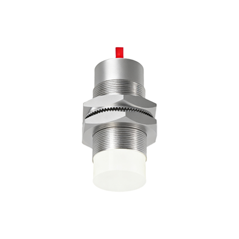
Electrical load and output configuration are common pitfalls. For a 3-wire DC sensor, confirm the load (e.g., a PLC input, relay coil) is connected correctly in series with the output wire. An open circuit in the load will mean no current flows, making the sensor appear dead. Check the load's impedance to ensure it falls within the sensor's rated specifications—both minimum and maximum. For a Normally Open (NO) sensor, the output switches on when a target is detected; for a Normally Closed (NC), the output switches off. Misunderstanding this configuration during installation or replacement can lead to the false conclusion of sensor failure. Always cross-reference the sensor's datasheet and the system's wiring diagram.
Environmental factors pose significant challenges. Accumulation of metal chips, dust, oil, or coolant on the sensor's face can insulate it and drastically reduce its effective range or block detection entirely. Regularly clean the sensing surface with appropriate solvents. Strong electromagnetic interference (EMI) from nearby variable frequency drives (VFDs), welding equipment, or large motors can disrupt sensor electronics. Ensure proper shielding, use twisted-pair cables for wiring, and maintain adequate physical separation from noise sources. Extreme temperatures, both high and low, can push the sensor beyond its operational specifications, causing temporary failure or permanent damage. Verify the sensor's IP rating is suitable for the environment (e.g., washdown, outdoor).
Finally, consider sensor selection and mechanical issues. Using an inductive sensor to detect a non-metallic object, or a capacitive sensor for an application with wildly fluctuating background conditions, is an application error. The sensor type must match the target material and environment. Mechanical misalignment, where the target does not pass directly in front of the sensing area, vibration loosening the mounting, or physical damage to the sensor housing from impacts can all lead to failure. Internally, electronic components can degrade over time or fail due to voltage spikes. If all external factors are ruled out, the sensor itself may be defective. Substituting with a known-good sensor of the same model is a conclusive test.
A methodical troubleshooting protocol—power, target, wiring, environment, and application—will resolve most instances of a non-responsive proximity sensor. Documenting findings and solutions contributes to a more robust maintenance knowledge base, preventing recurrence and minimizing future operational disruptions.