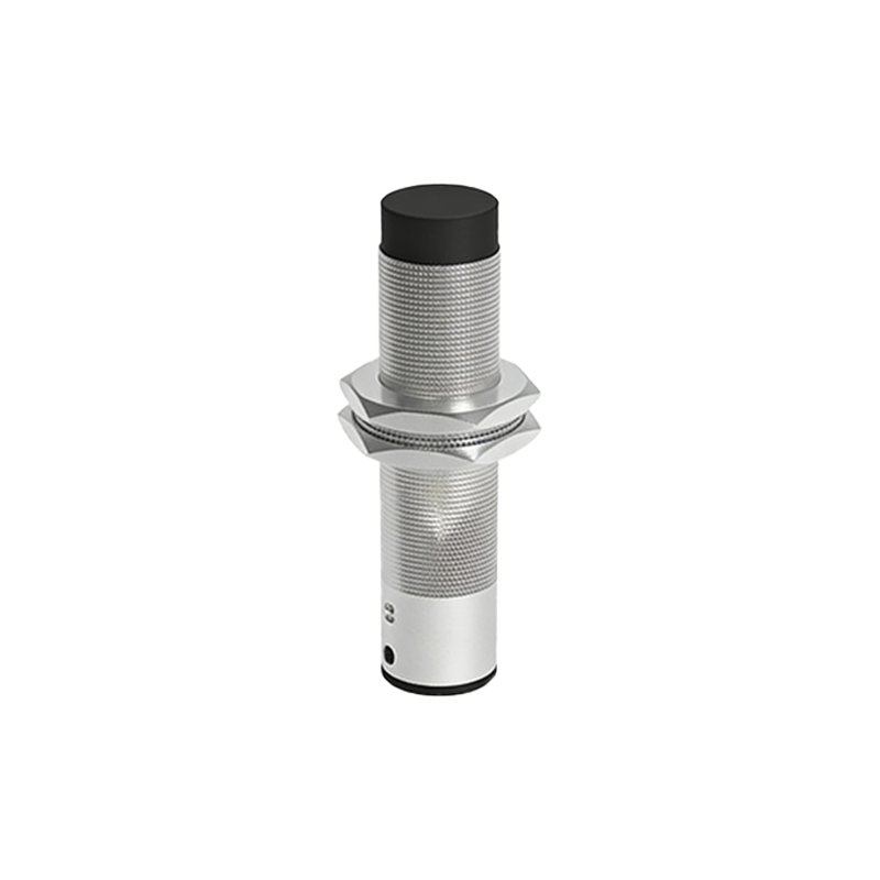
In industrial automation and control systems, proximity sensors are indispensable components for non-contact object detection. Among the various types, cylindrical threaded barrel sensors with pre-wired, quick-disconnect connectors—commonly referred to as "plug-in" or "direct-insertion" styles—are widely favored for their ease of installation and maintenance. A clear understanding of their wiring diagram is fundamental for ensuring reliable operation, safety, and system integrity. This guide provides a detailed, step-by-step breakdown of a standard 3-wire DC proximity sensor wiring configuration, the most prevalent in modern industrial applications.
Understanding the Core Components and Terminology
Before examining the diagram, it's crucial to define the key elements. A typical 3-wire DC sensor has three leads, distinguished by wire color, though colors can vary by manufacturer and region. The most common international standard (IEC) is:
Brown Wire: This is the positive supply line (+V). It connects to the positive terminal of the DC power source.
Blue Wire: This is the negative supply line or common (0V). It connects to the negative terminal of the DC power source.
Black Wire: This is the output signal line. The state of this wire (switched to V+ or 0V) changes based on the target's presence.
There are two primary output types, defined by the switching logic:
1. Normally Open (NO): The output circuit is open (no current flows) when no target is present. When a target enters the sensing range, the output circuit closes, and the black wire typically switches to the supply voltage (sourcing) or connects to 0V (sinking).
2. Normally Closed (NC): The opposite logic. The output circuit is closed when no target is present and opens when a target is detected.
Furthermore, outputs are categorized as Sourcing (PNP) or Sinking (NPN), describing the transistor type used for switching. This determines how the load (e.g., a PLC input, relay, or indicator light) is connected in the circuit.
The Standard Wiring Diagram: Sourcing (PNP) vs. Sinking (NPN)
Let's visualize two fundamental wiring schematics. Assume a 24V DC power supply, a common industrial voltage.
Diagram A: 3-Wire, DC, Sourcing (PNP) Proximity Sensor, Normally Open (NO)
Power Connection: The brown wire is connected to the +24V DC terminal. The blue wire is connected to the 0V/Common terminal.
Output Connection: The black wire (output) is connected to one terminal of your load (e.g., PLC input channel X0). The other terminal of the load is connected to the 0V/Common terminal.
Operation: When a target is detected, the internal PNP transistor activates. It sources current, meaning it provides the +24V supply voltage to the black wire. This voltage is then supplied to the load, completing the circuit to 0V, thus energizing the load. The load receives power from the sensor.
Diagram B: 3-Wire, DC, Sinking (NPN) Proximity Sensor, Normally Open (NO)
Power Connection: Identical to PNP: Brown to +24V, Blue to 0V.
Output Connection: The black wire (output) is connected to one terminal of your load. However, the other terminal of the load is now connected to the +24V supply terminal.
Operation: When a target is detected, the internal NPN transistor activates. It sinks current, meaning it provides a path to 0V. The black wire effectively connects the load to the 0V (common) line, completing the circuit from +24V, through the load, and to ground via the sensor. The load receives a ground path from the sensor.
Critical Installation and Troubleshooting Practices
1. Always Consult the Datasheet: Wire color codes can differ. The manufacturer's documentation is the ultimate authority for pinout, voltage range, output type (PNP/NPN, NO/NC), and sensing specifications.
2. Power Supply Considerations: Ensure the power supply voltage matches the sensor's rated voltage (e.g., 10-30V DC). Use a stable, regulated power supply. Incorrect polarity will damage the sensor.
3. Load Compatibility: Verify that the sensor's maximum output current rating is not exceeded by the load's current draw. For inductive loads like relays or solenoids, always use