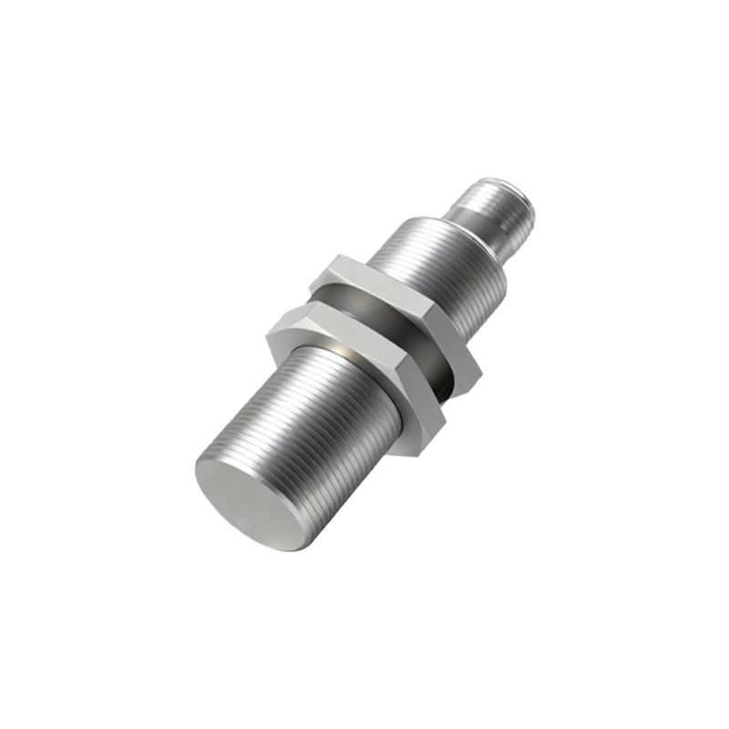
In industrial automation and control systems, proximity switch sensors play a critical role in detecting the presence or absence of objects without physical contact. These sensors, including inductive, capacitive, and photoelectric types, are valued for their reliability, durability, and precision. However, like any measurement device, they are subject to errors that can impact system performance. Understanding the acceptable error range for proximity switches is essential for engineers and technicians to ensure optimal operation and minimize downtime.
The error in proximity switches typically arises from several factors: manufacturing tolerances, environmental conditions, installation practices, and target material properties. For instance, inductive proximity sensors are sensitive to the conductivity and permeability of target materials. A standard inductive sensor calibrated for mild steel may exhibit significant error when detecting aluminum or copper due to differences in eddy current generation. This material-dependent error can range from 10% to 30% of the nominal sensing distance, depending on the sensor design and target composition.
Environmental influences such as temperature fluctuations, humidity, and electromagnetic interference (EMI) also contribute to sensor error. Most industrial proximity switches are rated for operation within specific temperature ranges, often -25°C to 70°C. Outside these limits, thermal expansion or contraction of internal components can alter the sensing characteristics, leading to errors of up to 10% in extreme cases. Similarly, high levels of EMI from nearby motors or power lines can cause false triggering or reduced sensitivity, adding unpredictable error margins.
Installation errors are another common source of inaccuracy. Improper mounting alignment, incorrect gap settings, or vibration can degrade sensor performance. For example, if a proximity sensor is mounted too close to a metal background, it may experience shielding effects that reduce its effective sensing range by 20% or more. Manufacturers typically provide installation guidelines specifying minimum clearance distances and alignment tolerances to mitigate such issues. Adhering to these recommendations is crucial for minimizing error.

The acceptable error for proximity switches varies by application and industry standards. In high-precision tasks like robotic assembly or semiconductor manufacturing, errors must be kept below 5% of the sensing distance to ensure repeatability and quality. For less critical applications, such as object counting in conveyor systems, errors up to 15% may be tolerable. International standards, such as IEC 60947-5-2, define performance criteria for proximity sensors, including repeatability, hysteresis, and temperature drift. These standards help engineers select sensors with error margins suitable for their specific needs.
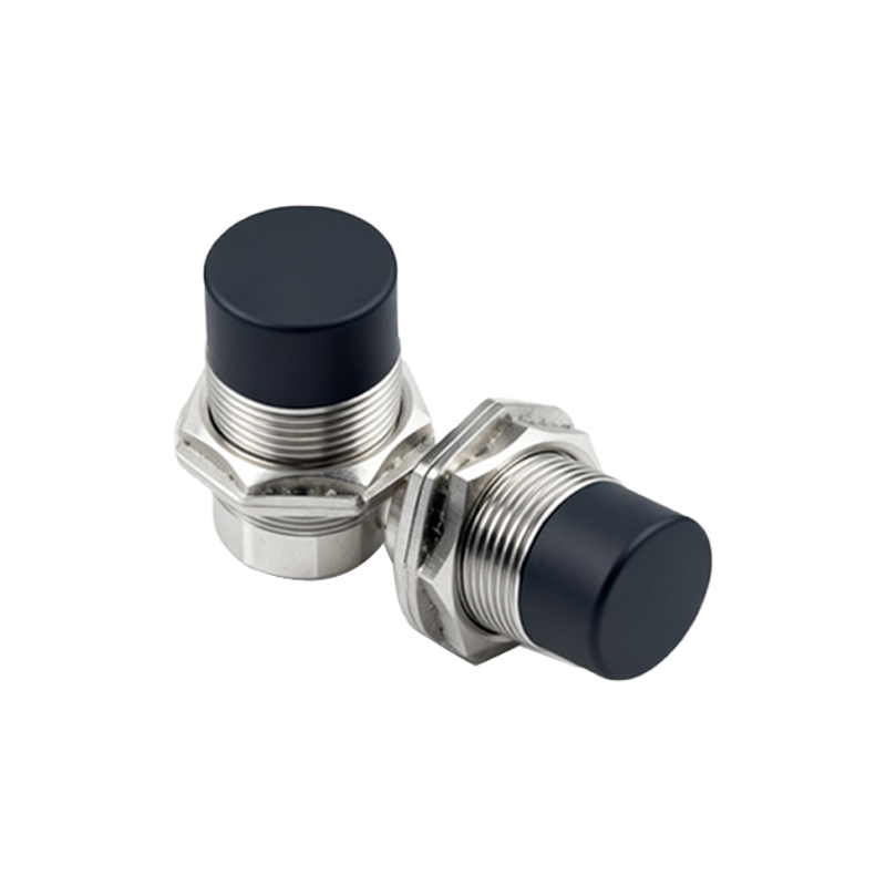
To quantify error, engineers often consider parameters like repeatability (the consistency of detection under identical conditions) and linearity (the deviation from an ideal response curve). High-quality proximity sensors typically offer repeatability within ±1% of the sensing distance and linearity errors below 5%. For example, a sensor with a 10mm nominal range might have a repeatability of ±0.1mm and a linearity error of ±0.5mm. These values are critical for applications requiring precise positioning or measurement.
Calibration and regular maintenance are key to managing sensor error over time. Proximity switches can drift due to aging components or contamination, leading to gradual increases in error. Implementing periodic calibration checks using certified targets and environmental controls can help maintain accuracy within acceptable limits. Additionally, choosing sensors with built-in diagnostics or temperature compensation features can reduce error susceptibility in dynamic industrial environments.
In summary, the acceptable error for proximity switch sensors depends on multiple factors, including sensor type, application requirements, and environmental conditions. While standard industrial sensors may tolerate errors up to 10-15% in non-critical uses, precision applications demand errors below 5%. By understanding error sources and adhering to best practices in selection, installation, and maintenance, engineers can optimize sensor performance and ensure reliable system operation. As technology advances, newer sensors with enhanced accuracy and compensation capabilities are reducing error margins, further improving automation efficiency.