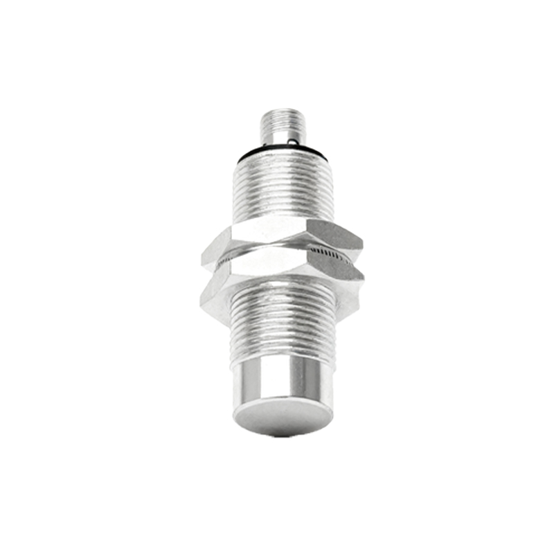
Infrared proximity sensors are essential components in modern industrial automation, offering non-contact detection capabilities for various applications. This article delves into the circuit design principles of infrared proximity sensors, focusing on key considerations for engineers in the electrical industry. The design typically involves an infrared emitter, a photodetector, and signal processing circuitry. The emitter, often an infrared LED, transmits modulated infrared light to avoid ambient light interference. The photodetector, such as a phototransistor or photodiode, receives reflected signals from objects within its range. A critical aspect of the circuit is the modulation and demodulation process, which enhances noise immunity. Using a 38 kHz modulation frequency is common, as it aligns with standard infrared receiver modules. The circuit must include amplifiers and filters to process weak signals from the detector. Operational amplifiers (op-amps) are employed to amplify the signal, while band-pass filters eliminate unwanted frequencies. Additionally, threshold comparators can be integrated to trigger outputs when an object is detected within a specific distance. Power management is vital, especially in battery-operated systems, requiring low-power components and efficient voltage regulation. For industrial environments, robustness against electrical noise and temperature variations is necessary. Shielding and proper grounding techniques should be implemented to prevent false triggers. Testing and calibration are final steps, ensuring the sensor meets accuracy and reliability standards. By adhering to these design principles, engineers can develop infrared proximity sensors suitable for applications like object detection, safety systems, and automated machinery.