Proximity sensors are essential components in modern industrial automation, offering non-contact detection of metallic or non-metallic objects. Among these, 12V DC proximity switches are widely favored for their compatibility with standard control systems, safety in low-voltage applications, and ease of integration. This guide provides a detailed overview of wiring a 12V proximity sensor switch, covering principles, step-by-step instructions, and practical tips to ensure reliable operation.
Understanding the basic working principle is crucial before proceeding with wiring. A 12V DC proximity sensor typically operates on electromagnetic or capacitive sensing technology. Inductive sensors detect metallic objects, while capacitive versions can sense both metallic and non-metallic materials. The sensor generates an output signal—usually as a normally open (NO) or normally closed (NC) contact—when an object enters its detection range. This signal is then used to control machinery, such as activating a relay, PLC input, or indicator light.
The wiring process begins with identifying the sensor’s terminals. Most 12V proximity switches have three wires: brown (positive), blue (negative), and black (output). Some models may include additional wires for diagnostic functions or multiple outputs. Always refer to the manufacturer’s datasheet for specific details, as wire colors can vary by brand. For a standard three-wire sensor, follow these steps:
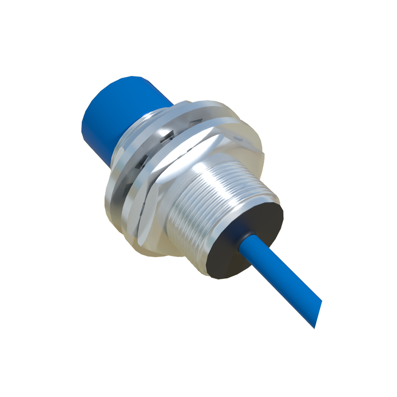
1. Power Connection: Connect the brown wire to the positive terminal of a 12V DC power supply. The blue wire should be linked to the negative terminal or ground. Ensure the power supply matches the sensor’s voltage rating (12V DC) and provides sufficient current, typically between 10-200mA depending on the model. Use shielded cables in electrically noisy environments to prevent interference.
2. Output Connection: The black wire carries the sensor’s output signal. For a basic setup, connect it to the input of a load, such as a relay coil, PLC digital input, or LED. If the sensor has a normally open configuration, the output circuit closes when an object is detected, allowing current to flow. For normally closed sensors, the circuit opens upon detection. Incorporate a protective device, like a fuse or surge protector, in series to safeguard against short circuits or voltage spikes.
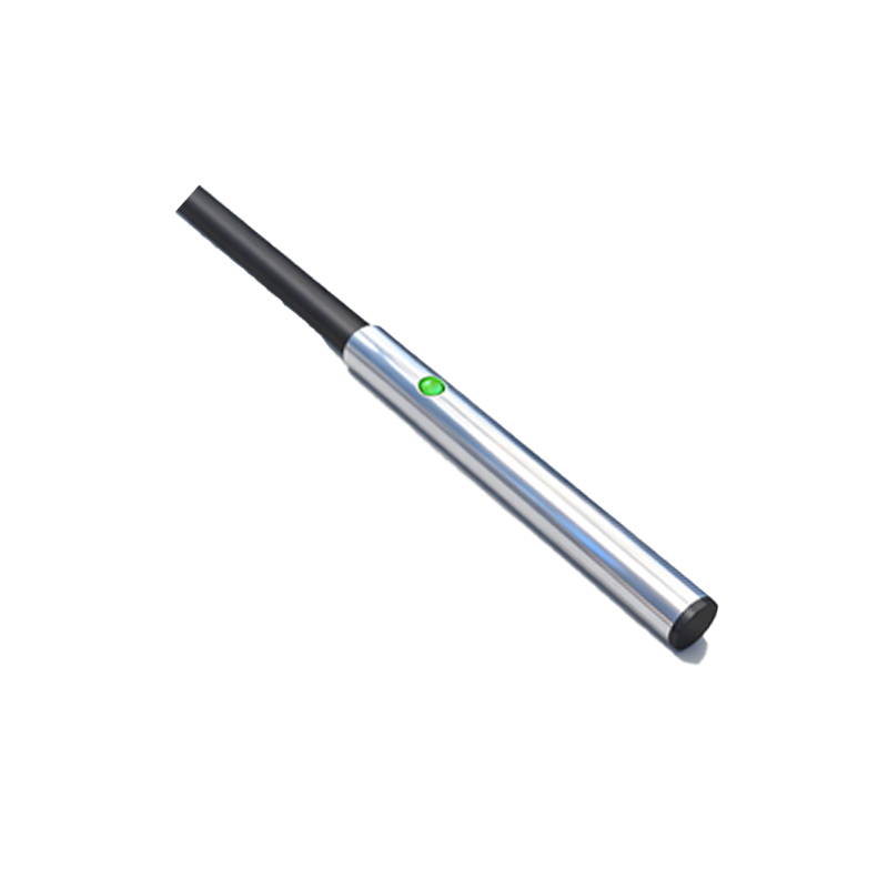
3. Load Integration: When connecting to a PLC or controller, verify the input specifications. Many PLCs accept 12V DC signals directly, but some may require additional resistors or optocouplers. For relay-driven applications, ensure the relay’s coil voltage matches the sensor’s output. Avoid exceeding the sensor’s maximum load current, usually specified in the datasheet, to prevent damage.
4. Testing and Calibration: After wiring, power on the system and test the sensor by introducing a target object within its sensing range. Use a multimeter to check voltage levels at the output terminal. Adjust the sensor’s sensitivity or detection distance if adjustable, and ensure stable operation without false triggers. Mount the sensor securely, considering factors like material composition, object size, and environmental conditions (e.g., temperature, humidity).
Common challenges in wiring include incorrect polarity, insufficient power supply, or electromagnetic interference. Double-check connections against the wiring diagram provided by the manufacturer. For long cable runs, use twisted-pair wires to reduce noise. In harsh industrial settings, consider sensors with IP67 or higher ratings for dust and water resistance.
Advanced applications may involve connecting multiple sensors in parallel or series, or integrating them with networking protocols like IO-Link for smart factory setups. Always prioritize safety by disconnecting power during installation and following local electrical codes.
In summary, wiring a 12V proximity sensor switch is straightforward with careful attention to terminal identification, power requirements, and load compatibility. Proper installation enhances system reliability, reduces downtime, and supports efficient automation processes. For complex setups, consulting an experienced engineer or technical support is recommended to optimize performance and longevity.