In industrial automation and control systems, proximity photoelectric sensors are indispensable components for non-contact detection of objects. Their reliability hinges significantly on correct installation and wiring. This guide provides a comprehensive overview of standard wiring diagrams, connection methods, and critical considerations for engineers and technicians.
A proximity photoelectric sensor typically consists of three core parts: an emitter (light source, often an LED), a receiver (phototransistor or photodiode), and a signal processing circuit. The wiring configuration is primarily determined by the sensor's output type and power supply requirements.
The most fundamental distinction lies between 2-wire, 3-wire, and 4-wire sensors. The 2-wire sensor is the simplest, acting like a switch in series with the load and power supply. It is easy to install but has a higher residual current and voltage drop, which can limit its use with sensitive loads. The positive (brown) wire connects to the DC positive supply, and the blue wire connects to the load, which then connects to the DC negative. For AC supplies, the brown wire connects to the phase (L) and the blue wire to the load and then neutral (N).
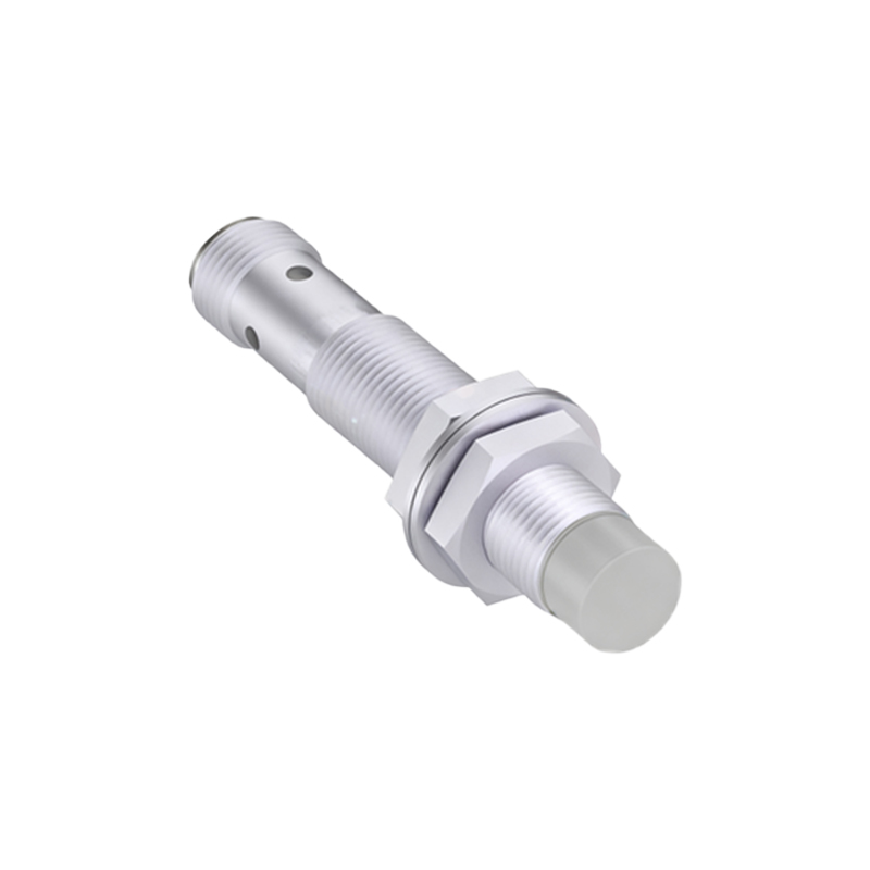
The 3-wire sensor is the most common in DC applications, offering separate paths for power and output, thus minimizing leakage current. It features three wires: brown (positive supply), blue (negative supply/0V), and black (output signal). Within 3-wire sensors, the output type is crucial: NPN (sinking) or PNP (sourcing). An NPN output switches the negative (0V) line to the load. In the wiring diagram, the brown wire connects to DC+, blue to DC-, and the black (NPN output) connects to one side of the load (e.g., a PLC input). The other side of the load is connected to DC+. Conversely, a PNP output switches the positive voltage line. Here, the black (PNP output) wire connects to the load, and the other side of the load connects to DC- (0V). Misidentifying NPN vs. PNP is a common installation error that prevents proper operation.
4-wire sensors typically provide two complementary outputs (e.g., one NPN and one PNP, or a NO/NC pair) from a single unit, offering greater flexibility. The wires are usually brown (DC+), blue (DC-), black (Output 1, often NO), and white (Output 2, often NC). The wiring follows the same logic as 3-wire sensors but allows control of two separate circuits based on the detection state.

For AC-powered sensors, the wiring is generally straightforward: brown to L (phase), blue to N (neutral), and black to the load. The load is then connected back to the N line. It is vital to check the sensor's voltage rating (e.g., 90-250V AC) and ensure proper grounding if applicable.
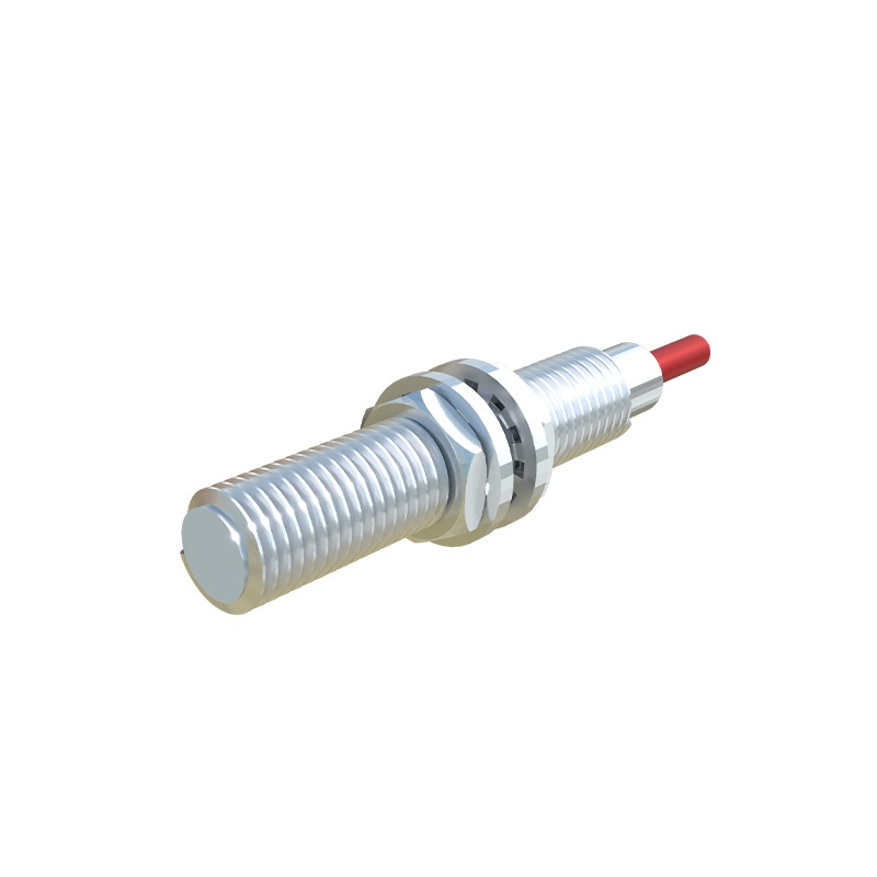
Shielded cables are highly recommended, especially in environments with significant electromagnetic interference (EMI). The cable shield should be grounded at one end only, typically at the control panel, to prevent ground loops. Always maintain proper separation between sensor cables and high-voltage power lines.
When connecting to a Programmable Logic Controller (PLC), attention to the input card type is paramount. A PLC with a sinking input (common positive) requires a sensor with a PNP (sourcing) output. A PLC with a sourcing input (common negative) requires an NPN (sinking) sensor. Refer to the PLC manual to confirm the input circuit configuration before wiring.
Key safety and performance practices include: Always disconnect power before wiring. Strictly adhere to the voltage and current specifications on the sensor datasheet. Use the correct wire gauge; typically, 18-22 AWG is sufficient for signal wiring. Ensure tight connections to avoid voltage drops or intermittent faults. For long cable runs, consider voltage drop calculations and potential signal degradation. Implement proper conduit or cable management to protect wires from physical damage, oils, and chemicals.
Many modern sensors feature diagnostic LEDs (power and output status). These LEDs are invaluable for troubleshooting. No light typically indicates a power or wiring fault. A solid power LED with no output change suggests misalignment, an out-of-range object, or a dirty lens. Always verify the sensing range, object material, color, and environmental conditions (dust, fog) as they affect photoelectric performance.
In summary, correctly interpreting and implementing the proximity photoelectric sensor wiring diagram is foundational for system integrity. By understanding the differences between 2-wire, 3-wire (NPN/PNP), and 4-wire configurations, and by following rigorous installation practices, engineers can ensure robust, reliable, and safe operation in any industrial automation setting. Always consult the specific manufacturer's