In industrial automation and control systems, proximity switch sensors are ubiquitous components, providing non-contact detection of metallic or other target objects. However, during system commissioning, troubleshooting, maintenance, or when a sensor fails, there are scenarios where temporarily bypassing or "shorting" the sensor becomes a necessary diagnostic or operational procedure. It is crucial to understand that this is a temporary measure for specific purposes and not a permanent solution. Incorrect bypassing can lead to equipment damage, safety hazards, or unintended machine operation. This guide details the correct methodologies for bypassing different types of proximity sensors.
Understanding Proximity Sensor Output Types
Before attempting any bypass, you must identify the sensor's output configuration, as the method differs significantly.
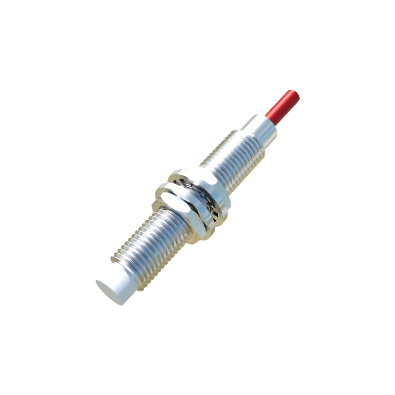
1. PNP (Sourcing) Sensors: The output acts as a positive voltage source. In the active state (target detected), it switches the positive supply voltage to the output line.
2. NPN (Sinking) Sensors: The output acts as a sink to ground. In the active state, it connects the output line to the circuit's common ground (0V).
3. Analog Output Sensors (e.g., 4-20mA, 0-10V): Bypassing typically involves simulating the signal with a calibrated source, which is a more advanced procedure.
4. Namur Sensors (Intrinsically Safe): Used in hazardous areas, these require specialized interface relays. Direct shorting is not applicable.
Safety and Preparatory Steps
Lock Out, Tag Out (LOTO): Always de-energize the control circuit or the entire machine following proper LOTO procedures before working on any wiring. Verify zero energy with a multimeter.
Consult Documentation: Refer to the sensor datasheet and the machine's electrical schematic to confirm the sensor type, wiring color code, voltage rating, and the connected load (e.g., PLC input, relay coil).
Gather Tools: You will typically need insulated screwdrivers, wire strippers, a multimeter, and suitable jumper wires with alligator clips or terminal connectors.
Bypass Procedures by Sensor Type
For a PNP (Sourcing) Proximity Switch:
A PNP sensor has three wires: Brown (+V supply, e.g., 24VDC), Blue (0V Common), and Black (Output). To simulate the sensor being in the "ON" state (target present):
1. After ensuring power is OFF and locked out, locate the sensor's connection point, often at a terminal block or the PLC input module.
2. Identify the Black (output) wire and the Blue (0V common) wire. Disconnect these wires from their terminals if necessary for a clean connection.
3. Using a jumper wire, create a connection between the terminal point for the Black wire (sensor output) and the terminal point for the Brown wire (+24V supply). This manually applies the supply voltage to the output line, mimicking the sensor's active state.
4. Important: Do not connect the Black output directly to the Blue (0V) wire on a PNP sensor, as this could cause a short circuit when the sensor is active internally.
For an NPN (Sinking) Proximity Switch:
An NPN sensor also has Brown (+V), Blue (0V), and Black (Output) wires. To simulate the "ON" state:
1. Follow the same safety and identification steps.
2. Identify the Black (output) wire and the Blue (0V common) wire.
3. Using a jumper wire, create a connection between the terminal point for the Black wire (sensor output) and the terminal point for the Blue wire (0V common). This manually sinks the output line to ground, mimicking the sensor's active state.
4. Important: Do not connect the Black output directly to the Brown (+V) wire on an NPN sensor, as this could cause a short circuit.
Bypassing at the PLC Input Module:
Often a safer and more convenient point is at the PLC digital input card.
1. Identify the specific input channel (e.g., I0.4) corresponding to the sensor from the schematic.
2. For a 24VDC sinking input card (common to PNP sensors), place a jumper from the input terminal to a nearby +24VDC terminal on the card's power bus.
3. For a 24VDC sourcing input card (common to NPN sensors), place a jumper from the input terminal to a nearby 0VDC terminal on the card's power bus.
This method avoids disturbing field wiring.
Verification and Restoration