In industrial automation and control systems, three-wire proximity sensors are widely used for their reliability and ease of integration. These sensors detect the presence or absence of an object without physical contact, making them essential in applications ranging from manufacturing lines to safety mechanisms. A key aspect of their operation is the voltage configuration, which directly impacts performance, compatibility, and safety. This article delves into the voltage characteristics of three-wire proximity sensors, explaining wiring principles, common voltage standards, and practical considerations for engineers.
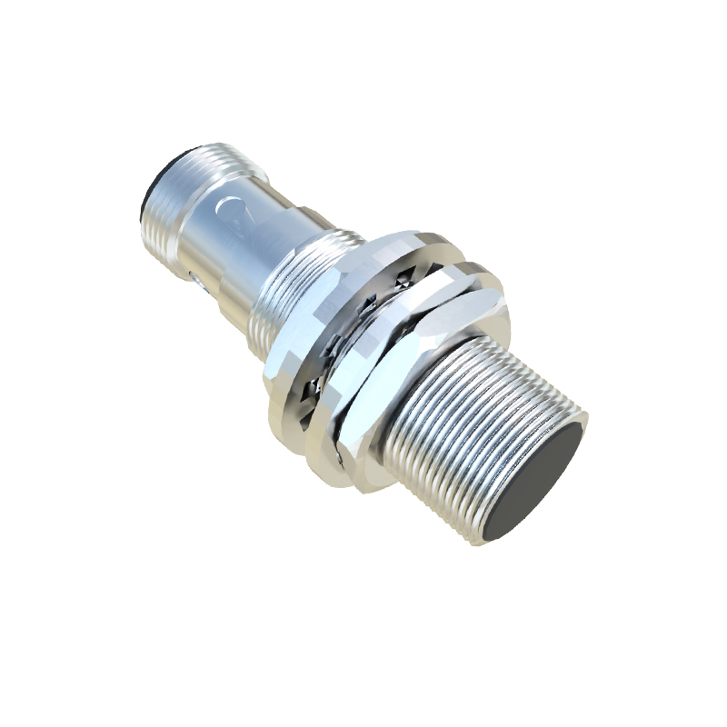
Three-wire proximity sensors typically consist of three connections: positive (V+), negative (V- or ground), and output (signal). The voltage across these wires defines the sensor's operating range and output type. Most industrial sensors operate on direct current (DC) voltages, with common standards being 10-30V DC or 5-24V DC, depending on the model and application. The positive wire supplies power to the sensor's internal circuitry, while the negative wire completes the circuit. The output wire provides a switching signal—either sourcing (PNP) or sinking (NPN)—that indicates detection. For instance, in a 24V DC PNP sensor, the output voltage switches to near 24V when an object is detected, whereas in an NPN sensor, it drops to near 0V.
Understanding voltage ratings is crucial for system compatibility. Incorrect voltage can lead to sensor failure, erratic behavior, or damage to connected devices like programmable logic controllers (PLCs). Engineers must match the sensor's voltage with the power supply and load requirements. For example, a 12V DC sensor should not be used in a 24V DC circuit without proper voltage regulation. Additionally, voltage fluctuations in industrial environments can affect sensor accuracy. It's recommended to use stable power sources and consider factors like cable length, which can cause voltage drops over long distances. Shielding and proper grounding help mitigate electrical noise, ensuring reliable signal transmission.
When installing three-wire proximity sensors, follow wiring diagrams provided by manufacturers. Typically, brown wires denote positive, blue wires indicate negative, and black wires represent the output. Always verify voltage with a multimeter before connection to prevent reverse polarity, which can permanently damage the sensor. For troubleshooting, check voltage levels at each wire: the positive should match the supply voltage, the negative should be at ground potential, and the output should toggle between high and low states upon detection. If the output fails to switch, inspect for issues like insufficient voltage, object misalignment, or sensor wear.
In summary, the voltage of three-wire proximity sensors is a fundamental parameter that influences their functionality and integration. By adhering to standard voltage ranges, ensuring proper wiring, and accounting for environmental factors, engineers can optimize sensor performance for diverse industrial applications. As technology advances, sensors with wider voltage tolerances and smart features are emerging, offering greater flexibility and efficiency in automation systems.