Proximity sensors are indispensable components in modern industrial automation, providing non-contact detection of metallic or non-metallic objects. An open circuit fault, where the electrical path is interrupted, is a common yet critical malfunction that can halt production lines and cause significant downtime. Understanding the causes, diagnostic procedures, and corrective actions is essential for maintenance engineers and technicians.
The primary symptom of an open circuit is the sensor failing to detect a target within its specified sensing range, even when the target is correctly positioned. The sensor's output may remain permanently OFF (or ON, depending on its normal state configuration), and the diagnostic LED, if present, often indicates a fault condition, such as a steady or flashing red light, as opposed to the normal operational indication.
A systematic approach to troubleshooting is paramount. Begin by ensuring all safety protocols are followed, including lockout/tagout procedures to isolate the equipment from power sources. The first step is visual inspection. Examine the sensor housing for any signs of physical damage, cracks, or deformation caused by impact or excessive vibration. Check the cable thoroughly, from the sensor connection point to the terminal block or connector. Look for cuts, abrasions, pinch points, or burn marks. Pay close attention to the cable entry point into the sensor, a common failure area due to stress.
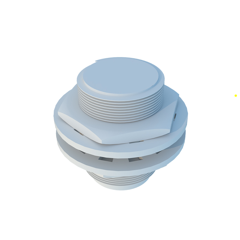
Next, verify the electrical connections. Loose wiring at the terminal blocks, corroded contacts, or a poorly crimped connector pin can create an open circuit. Tighten all terminal screws and inspect for signs of oxidation or carbon buildup. If the sensor uses a quick-disconnect connector, disconnect and reconnect it several times to wipe the contacts clean.
Electrical testing with a multimeter is the definitive diagnostic step. For a 3-wire DC sensor (the most common type), first confirm power supply integrity. With power OFF, disconnect the sensor wiring. Measure the voltage between the positive supply line (typically brown) and the negative/common line (typically blue) at the source to ensure it matches the sensor's rated voltage (e.g., 10-30V DC). With power restored and the sensor connected, measure the voltage between the signal output line (typically black) and the negative line. When a valid target is presented, the output voltage should switch from near supply voltage (for a PNP normally open sensor) to near 0V, or vice-versa. If the output voltage does not change and remains at an abnormal level (e.g., 0V or floating), it suggests an internal sensor fault.
Resistance checks can be performed with power completely isolated. For a 2-wire AC/DC sensor, measuring the resistance across its two wires might show an extremely high resistance (megohms or infinity) in case of an open circuit, compared to a finite resistance when functional. For 3-wire sensors, consulting the manufacturer's datasheet is crucial, as internal circuitry can make resistance readings between pins misleading. A more reliable method is to check for continuity along the cable. Disconnect both ends of the sensor cable. Use the multimeter's continuity or resistance function to check each wire from end to end. A continuous wire will show very low resistance (a few ohms); an open wire will show "OL" or infinite resistance, confirming a break within the cable.
Common root causes of open circuits include mechanical stress from constant flexing or pulling on the cable, exposure to excessive heat that degrades wire insulation and conductors, chemical corrosion from oils or solvents, and internal component failure due to voltage spikes, overcurrent, or aging. In high-vibration environments, wire strands can fatigue and break internally while the insulation remains intact.
Once the fault is isolated, corrective action can be taken. If the issue is a damaged cable, the best practice is to replace the entire sensor if it has an integral, non-removable cable. For sensors with removable cable connectors (e.g., M8 or M12), simply replace the faulty cable assembly. If the fault is conclusively inside the sensor housing (confirmed by testing a known-good cable on it), the sensor unit itself must be replaced. Temporary repairs like splicing a broken cable are generally not recommended in industrial settings due to reliability and safety concerns, but if absolutely necessary, use proper solder and insulation techniques followed by protective conduit.
Preventive measures are key to avoiding recurrence. Use cable carriers or strain relief glands to minimize flexing stress. Select sensors with appropriate IP (Ingress Protection) ratings for the environment (e.g., IP67 for washdown areas). Ensure proper installation with adequate clearance and mounting rigidity to avoid vibration. Implement surge protection devices on supply lines in areas prone to electrical noise. Regularly include sensor functionality checks in preventive maintenance schedules.
In conclusion, an open circuit in a proximity sensor is a resolvable issue. By methodically performing visual inspections, checking connections, and conducting electrical tests