In the realm of industrial automation and safety systems, glass proximity sensors play a pivotal role. Their non-contact detection capability, immunity to environmental factors like dust and moisture, and high reliability make them indispensable in applications ranging from automotive assembly lines to food processing machinery. However, ensuring their optimal performance requires precise and reliable testing. This article delves into the specialized instruments used for testing glass proximity sensors, outlining their functionalities, key parameters, and best practices for electrical engineers and maintenance professionals.
The core principle behind inductive proximity sensors, including those with glass faces, involves generating an electromagnetic field. When a metallic target enters this field, it induces eddy currents, causing a change in the sensor's oscillation amplitude. This change is detected and converted into a switch signal. Glass-faced variants offer superior chemical resistance and are ideal for harsh environments where standard plastic sensors might degrade. Testing these sensors is not merely about verifying a simple on/off state; it involves quantifying their performance against specifications.
Essential Testing Instruments and Their Functions:
1. Digital Multimeter (DMM): A fundamental tool for any electrical engineer. It is used primarily for:
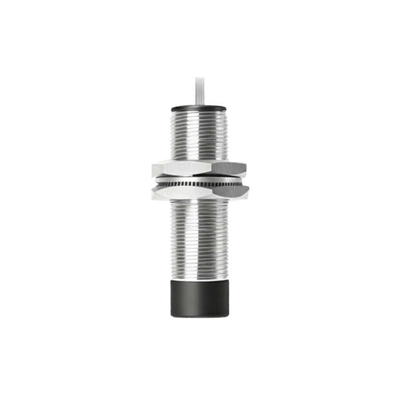
Supply Voltage Verification: Confirming the sensor is receiving the correct DC voltage (e.g., 10-30V DC) as per its datasheet.
Output State Measurement: In a 3-wire configuration, measuring the voltage at the output line to verify the switching state (high or low) in relation to the target's presence.
Current Draw Measurement: Checking the sensor's quiescent and active current consumption to ensure it is within specified limits and not indicative of internal faults.

2. Oscilloscope: For advanced diagnostics, an oscilloscope is invaluable. It allows engineers to:
Visualize Switching Characteristics: Observe the rise time, fall time, and any ringing or noise on the output signal. A clean, fast switch is crucial for high-speed applications.
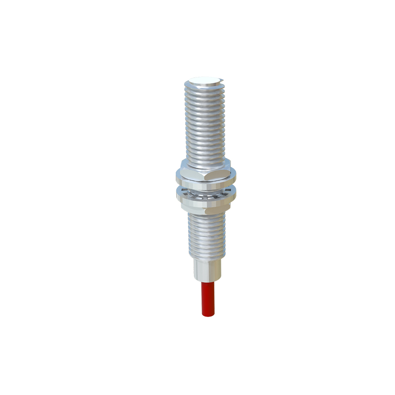
Monitor Power Supply Integrity: Detect any ripple or noise on the supply line that could affect sensor performance.
Analyze PWM Outputs: Some sensors provide proportional or PWM (Pulse Width Modulation) outputs. An oscilloscope is essential for measuring duty cycle and frequency accuracy.
3. Target Simulator / Thickness Gauge Set: This is a critical instrument specifically for proximity sensor testing. It consists of precision-machined metal targets (often steel) of standardized thickness (e.g., 1mm) mounted on a calibrated measuring scale.
Function: It is used to measure the switching distance (Sn). The sensor is powered on, and the target is slowly moved towards the active face. The exact distance at which the output switches is the actual switching point. This is compared to the rated operating distance (Sr) specified by the manufacturer. A significant deviation indicates potential issues.
Hysteresis Measurement: The target simulator also allows measurement of hysteresis—the difference between the switch-on and switch-off points. Proper hysteresis prevents chattering when a target is at the borderline of the sensing range.
4. Programmable Logic Controller (PLC) or Dedicated Sensor Tester: In an integrated system, a PLC can be used to monitor the sensor's digital signal. Dedicated handheld sensor testers are also available. These devices often combine functionality: they provide a stable power source, have a built-in LED to indicate switching status, and sometimes can simulate a load (like an LED or relay), providing a complete functional check in the field.
5. Environmental Chamber: For qualification and rigorous testing, sensors may be tested under varying environmental conditions. While not a routine field instrument, chambers that control temperature and humidity are used to verify sensor performance across its specified operating range, ensuring the glass encapsulation and internal electronics remain stable.
Key Testing Parameters and Procedure:
A standard test procedure should encompass the following steps:
1. Visual Inspection: Check the glass face for cracks, chips, or buildup. Clean the surface with appropriate solvents.
2. Electrical Connection: Wire the sensor correctly according to its type (PNP/NPN, NO/NC) to a known-good power supply and measurement instrument.
3. Supply Check: Use the DMM to verify stable, correct supply voltage at the sensor terminals.
4. Switching Distance Test: Using the target simulator, measure the actual switching distance for the standard target. Perform multiple approaches to ensure repeatability.
5. Output Signal Quality: Use an oscilloscope to examine the output waveform for cleanliness and correct voltage levels when switched.
6. Load Test: Connect the sensor to its intended load (or an equivalent) to ensure it can drive it effectively without voltage drop or overheating.
7.