Magnetic door sensors, also known as proximity switches or reed switches, are fundamental components in security systems, automation, and access control. Proper wiring is crucial for reliable operation. This guide provides a step-by-step overview of wiring a standard two-wire Normally Open (NO) magnetic door sensor switch, covering principles, tools, and best practices.
Understanding the Basics
A typical magnetic door sensor consists of two parts: a switch unit (containing the reed switch) and a separate magnet. When the magnet is brought close to the switch (door closed), the reed contacts inside close, completing a circuit. When the magnet is moved away (door opened), the contacts spring open, breaking the circuit. This state change is detected by a control panel, alarm system, or PLC. Most basic sensors are two-wire devices, operating as a simple dry contact switch. They do not have polarity; either wire can connect to the common (C) or normally open (NO) terminal on the supporting device.
Required Tools and Materials
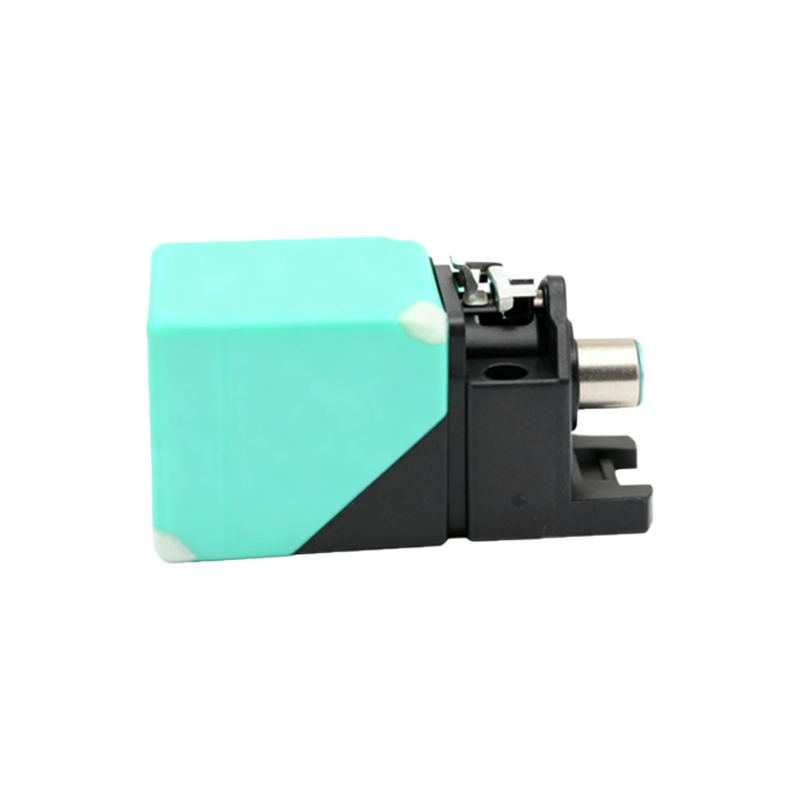
Magnetic door sensor (NO type)
Low-voltage wire (e.g., 22/2 or 22/4 stranded cable for longer runs)
Wire strippers/cutters
Screwdrivers
Multimeter (for verification)
Control device (alarm panel, PLC input module, etc.)
Step-by-Step Wiring Procedure
1. Power Down: Always disconnect power from the control panel or system before beginning any wiring work. Verify with a multimeter.
2. Plan the Run: Determine the path for the wire from the sensor location (door/window frame) to the control device. Ensure the wire is protected from physical damage and away from AC power lines to prevent interference.
3. Prepare the Sensor: The switch housing typically has two screw terminals. Strip approximately 1/4 inch (6mm) of insulation from the ends of your two-conductor wire.
4. Connect to the Sensor: Attach one wire to each terminal on the sensor. The order does not matter for a non-polarized switch. Tighten the terminal screws securely to ensure a solid connection.
5. Run the Cable: Route the cable to the control device's location. Use cable clips or conduit for a neat and secure installation.
6. Connect to the Control Device: Locate the appropriate terminal zone for protective loops or monitor inputs on your control panel. For a basic alarm zone, you will often connect to terminals labeled for a "Normally Open" circuit. For example:
Connect one sensor wire to the zone's "C" (Common) terminal.
Connect the other sensor wire to the zone's "NO" (Normally Open) terminal.
If required by your panel, install an end-of-line resistor (EOLR) across these terminals or in series at the sensor for supervised circuits. Consult your panel manual.
For a PLC digital input, connect one wire to the common (0V/DC-) and the other to the specific input point (e.g., DI1).
7. Secure and Terminate: Neatly dress all wires in the panel, secure them with cable ties, and ensure no loose strands could cause shorts.
Testing and Verification
1. Restore power to the control system.
2. With the magnet and sensor aligned (door simulated as closed), use a multimeter in continuity mode to check for a closed circuit (near 0 ohms) at the sensor terminals or at the panel zone terminals.
3. Separate the magnet from the sensor (door simulated as open). The multimeter should show an open circuit (infinite resistance/O.L.).
4. Activate the monitoring system. The control panel or PLC should register a "secure" or "normal" state when the contacts are closed and a "fault" or "triggered" state when they are open. Walk-test the sensor several times.
Important Considerations and Best Practices
Sensor Alignment: During mounting, ensure the magnet and switch are perfectly aligned within their specified gap (usually 1/2 inch or less). Misalignment can cause intermittent failure.
Wire Type: Use stranded wire for flexibility, especially for doors that move. Avoid solid core wire in moving applications.
Supervised Circuits: For security systems, using an End-of-Line Resistor (EOLR) is standard. It allows the panel to distinguish between a door opening, a wire cut (tamper), or a short circuit.
Environmental Factors: Protect connections from