In industrial automation and control systems, proximity switches are indispensable components for non-contact detection of metallic or other objects. A common and often perplexing issue encountered by maintenance technicians and engineers is a proximity switch sensor that remains in a permanently "ON" or activated state. This condition, where the output signal is continuously high regardless of the target's presence, can halt production lines and lead to significant downtime. Understanding the root causes and systematic troubleshooting steps is crucial for efficient resolution.
The fundamental principle of operation varies by type—inductive, capacitive, or magnetic—but the symptom of constant activation points to a failure in the sensor's ability to correctly interpret its environment or a failure in its output circuitry. For inductive sensors, the most common type used for metal detection, this typically means the oscillator circuit is not functioning correctly, or external factors are causing continuous oscillation.
Several primary causes can lead to a proximity sensor staying on constantly:
1. Sensor Damage or Internal Failure: Physical impact, excessive vibration, or ingress of contaminants like metal chips, coolant, or oil can damage the internal electronics. A short circuit in the oscillator circuit or the output switching element (typically a transistor) can cause it to latch in the "on" state. Overvoltage events from power surges or incorrect wiring are also common culprits for internal component failure.
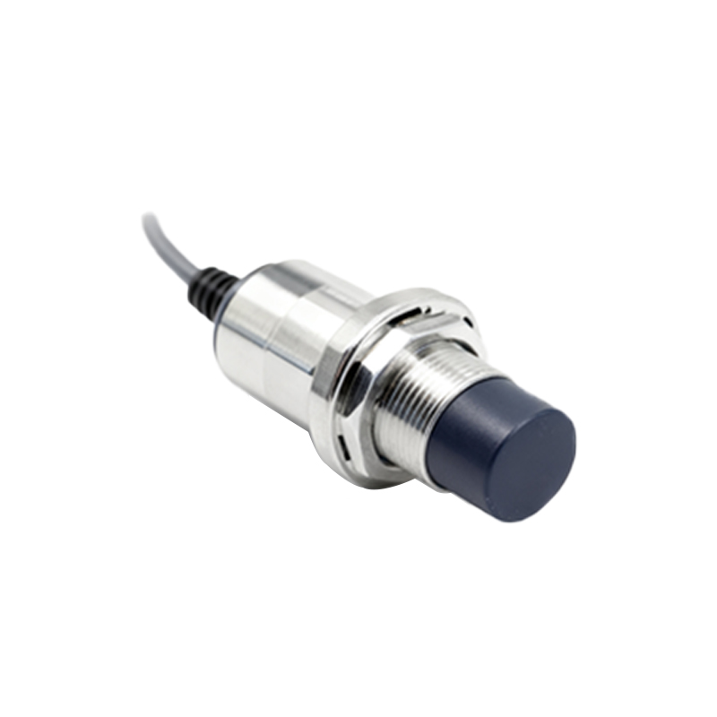
2. Incorrect Installation or Sensing Distance Issues: Installing the sensor too close to a metallic background (like a machine frame) can cause it to sense this background as a permanent target, a phenomenon known as "background suppression" failure. Exceeding the specified sensing distance for the application, even without a background, can sometimes cause unstable operation leading to a constant on signal. Ensuring the correct mounting flush or non-flush as per specifications is vital.
3. Electrical Interference and Noise: Industrial environments are rich sources of electromagnetic interference (EMI) from motors, variable frequency drives (VFDs), welding equipment, and power lines. This electrical noise can be induced into the sensor's signal lines or power supply, fooling the internal circuitry into registering a false detection. Poor shielding or long, unshielded cable runs alongside power cables exacerbate this issue.
4. Power Supply Problems: An unstable or out-of-specification power supply voltage can cause erratic sensor behavior. Voltage spikes or drops outside the sensor's operating range (e.g., 10-30V DC) can force the output stage into a permanent conductive state. Similarly, using an AC power supply on a DC-rated sensor, or vice versa, will cause immediate failure and likely a permanent on or off state.
5. Load or Wiring Faults: A short circuit in the load connected to the sensor's output (e.g., the PLC input module or a relay coil) can sometimes back-feed or create a path that makes it appear the sensor is always on. Incorrect wiring, such as connecting a PNP (sourcing) sensor to a circuit expecting an NPN (sinking) input, or mixing up the Brown (+), Blue (-), and Black (output) wires on a standard 3-wire DC sensor, can lead to improper operation.
6. Environmental Factors: Accumulation of metallic dust directly on the active face of an inductive sensor can act as a permanent target. For capacitive sensors, changes in humidity, moisture buildup, or contamination with non-metallic but dielectric materials can alter the sensing field and cause constant activation.
Systematic Troubleshooting Approach:
A methodical approach is key to diagnosing the problem.
Step 1: Isolate the Sensor. Disconnect the sensor from its load and power. Using a multimeter, check the output directly at the sensor's terminals while applying power. If the output remains high with no target present, the fault is likely internal to the sensor.
Step 2: Check Power and Environment. Verify the power supply voltage is stable and within range at the sensor's terminals under load. Inspect the sensor face for contamination and ensure the mounting distance and environment comply with specifications.
Step 3: Inspect Wiring and Load. Check for short circuits, damaged cables, or incorrect connections. Temporarily connect the sensor to a known-good load (like a test lamp or multimeter) to rule out load-side issues.
Step 4: Assess Electrical Noise. If interference is suspected, try powering the sensor from a separate, clean power source. Install ferrite cores on the cable near the sensor, ensure proper grounding, and reroute cables away from noise sources.
Step 5: Substitute and Confirm. The most definitive test is to replace the suspect sensor with a known-good unit of the same model. If the problem disappears, the original sensor is faulty.
Preventive measures include selecting sensors