In industrial automation and control systems, 2-wire proximity sensors are fundamental components for non-contact detection of metallic or non-metallic objects. Unlike their 3-wire or 4-wire counterparts, these sensors simplify wiring by combining the power supply and signal output into a single pair of wires. However, this simplicity can sometimes make troubleshooting more challenging. Determining whether a 2-wire proximity sensor is functioning correctly is a critical skill for maintenance technicians and engineers. This guide outlines a systematic, practical approach to measuring and verifying the health of a 2-wire DC proximity sensor.
First, understand the basic operating principle. A 2-wire DC proximity sensor is essentially a switch in series with the power supply. In its normal state (no target present), a small leakage current, often called the off-state current or residual current, flows through the sensor. When a target enters the sensing range, the sensor's internal switching element (typically a transistor) turns on, allowing a significantly higher on-state current to flow, which is sufficient to drive the load (e.g., a PLC input module, relay coil). The key parameters to verify are this switching behavior, the current values, and the voltage drop across the sensor.
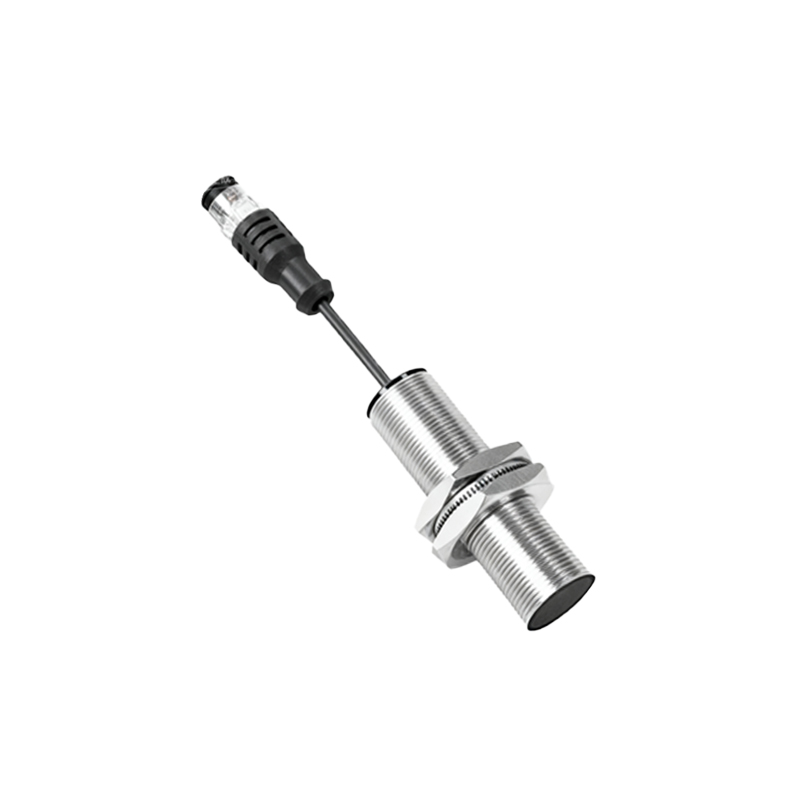
Essential Tools for Testing:
1. A digital multimeter (DMM) capable of measuring DC voltage and current.
2. A regulated DC power supply matching the sensor's voltage rating (e.g., 10-30V DC). Alternatively, you can use the existing system voltage if it is safe and accessible.

3. A known-good target object specified for the sensor (correct material and size).
4. (Optional) A dummy load resistor to simulate the PLC input, if testing off-line. A 1-2 kΩ resistor is often suitable.
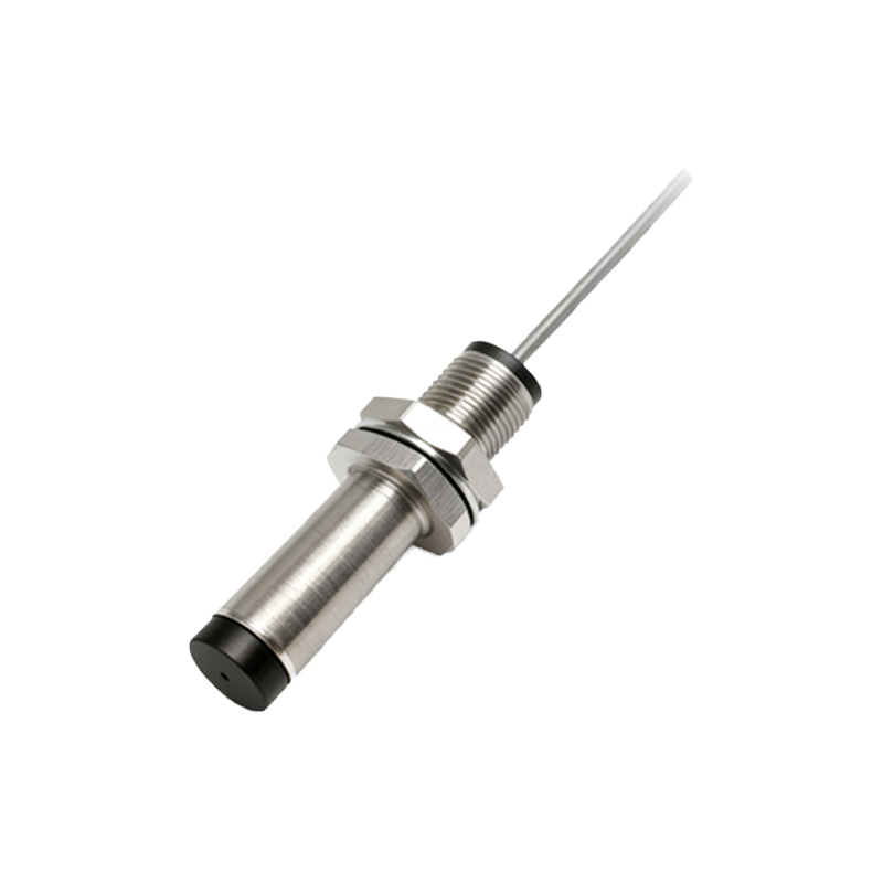
Step-by-Step Testing Procedure:
1. Visual and Physical Inspection:
Before any electrical test, perform a thorough inspection. Check the sensor's housing for cracks, dents, or signs of impact. Examine the cable and connection points for damage, fraying, or corrosion. Ensure the sensing face is clean and free from debris, metal chips, or buildup that could affect performance. Verify the part number and specifications (PNP/NPN sinking/sourcing compatibility, voltage range, sensing distance) match the application requirements.
2. Off-State Test (No Target Present):
Disconnect the sensor from the control circuit if possible. Connect the sensor in series with your DC power supply and the multimeter set to measure DC current (µA/mA range). Alternatively, you can wire the sensor with a dummy load resistor and measure voltage drops.
Apply the nominal operating voltage (e.g., 24V DC).
With no target near the sensing face, measure the current flowing through the circuit. This is the off-state current or leakage current. Consult the sensor's datasheet for the typical value, which is usually below 2 mA. A reading significantly higher than the datasheet specification may indicate internal damage or failure.
Simultaneously, measure the voltage drop across the sensor's two wires. In the off-state, most of the supply voltage will be dropped across the sensor, meaning the voltage at the output wire (relative to negative) will be very low—close to 0V for a leaking NPN-type or near supply voltage for a leaking PNP-type. This low signal is interpreted by the PLC as an "OFF" state.
3. On-State Test (Target Present):
Introduce the specified target object to the sensor's sensing face. Move it slowly and axially towards the face until you expect activation.
Observe the current reading on your multimeter. It should jump to a higher value, the on-state current. This current must be sufficient to drive the connected load. A typical on-state current for a 2-wire sensor might be 5-20 mA, depending on the load. A failure to increase current indicates the internal switch is not activating.
Measure the voltage drop across the sensor again. When activated, the voltage drop across the sensor becomes very low (typically 1-3V, known as the saturation voltage or voltage drop). Consequently, the output wire voltage should now be close to the supply voltage (for an NPN-type, pulling up to positive) or close to 0V (for a PNP-type, pulling down to negative), signaling an "ON" state to the PLC. If the voltage drop remains high when a target is present, the sensor is likely faulty.
4. Sensing Distance and Hysteresis Check:
Using the target, determine the actual operating point—the distance where the sensor reliably switches on. Compare this to the