Laser sensors are indispensable components in modern industrial automation, offering high precision for detection, measurement, and positioning tasks. Proper wiring is crucial to ensure their reliability, safety, and optimal performance. This guide provides a comprehensive, step-by-step approach to wiring laser sensors, tailored for engineers and technicians in the electrical and automation fields.
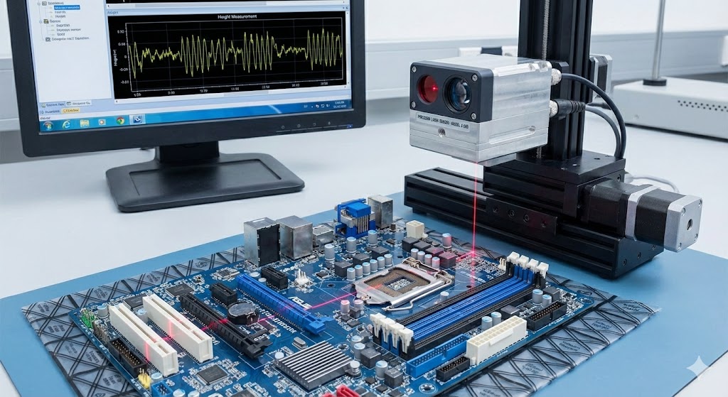
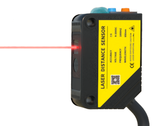
First, understand the basic components of a typical laser sensor. Most industrial laser sensors consist of a sensing head, a control unit or amplifier, and connection cables. The sensing head emits a laser beam and receives the reflected signal. The control unit processes this signal and provides output. Common output types include digital (PNP/NPN) and analog (4-20 mA, 0-10 V). Always refer to the sensor’s datasheet for specific specifications, including voltage ratings, output types, and pin configurations.
Before starting any wiring work, ensure all power sources are disconnected to prevent electrical shock or damage to the sensor. Gather necessary tools: appropriate cables (shielded cables are recommended for noise reduction), wire strippers, screwdrivers, and a multimeter for verification.
Step 1: Identify Power Supply Requirements
Most laser sensors operate on DC voltage, commonly 12-24 VDC. Check the sensor’s label or manual for the exact voltage range. Using an incorrect voltage can permanently damage the sensor. Connect the positive wire (typically brown or red) to the DC positive terminal and the negative wire (blue or black) to the DC negative terminal. Ensure the power supply is stable and within the sensor’s tolerance.
Step 2: Connect the Output Wires
The output configuration depends on your control system. For digital PNP sensors (sourcing), the output wire (usually black) provides a positive voltage when activated. Connect it to the input of a PLC, relay, or other controller. For NPN sensors (sinking), the output provides a ground connection when activated. Analog sensors have separate wires for analog output signals; for example, a 4-20 mA output requires connecting the output wire to the analog input module of a controller. Always verify the load compatibility to avoid overcurrent.
Step 3: Implement Shielding and Grounding
Industrial environments often have electromagnetic interference (EMI) that can affect sensor accuracy. Use shielded cables and connect the shield to a proper ground point at one end only (usually at the control panel) to avoid ground loops. Ensure the grounding is solid and low-resistance.
Step 4: Wire Additional Functions
Some laser sensors feature auxiliary functions like teach-in, synchronization, or alarm outputs. Refer to the manual for specific wiring of these pins. For instance, a teach-in input might require a momentary switch connection to program detection thresholds.
Step 5: Secure Connections and Test
After wiring, double-check all connections for tightness and correct polarity. Insulate exposed wires with terminal blocks or connectors. Once secured, apply power. Use a multimeter to measure voltage at the sensor terminals and output points. Test the sensor by placing an object within its detection range; observe the output indicator LED or measure the output signal. For analog sensors, verify the output current or voltage corresponds to the measured distance as per the datasheet.
Common pitfalls to avoid include reverse polarity, loose connections, inadequate grounding, and ignoring environmental factors like ambient light or reflective surfaces that may interfere with the laser beam. For long-distance wiring, consider voltage drop and use thicker gauge wires if necessary.
In summary, correct wiring of laser sensors involves careful planning, adherence to specifications, and rigorous testing. By following these steps, engineers can ensure seamless integration into automated systems, enhancing productivity and reducing downtime. Always prioritize safety and consult manufacturer guidelines for model-specific details.