Have you ever wondered how automatic doors know when to open, or how your phone screen turns off when you hold it to your ear? The magic behind these everyday conveniences is often a small but mighty device: the proximity sensor. While they seem complex, the basic principle is quite accessible. This hands-on experiment will guide you through building a simple infrared (IR) proximity sensor circuit. It's a perfect weekend project for students, hobbyists, or anyone curious about the electronics embedded in the world around us.
To begin, let's gather the necessary components. You won't need advanced tools or a professional lab. The core parts include an IR LED (the transmitter), a photodiode or phototransistor (the receiver), a 220-ohm resistor, a 10k-ohm resistor, a standard LED (for visual output), and an LM358 operational amplifier (op-amp) chip. You'll also need a breadboard, jumper wires, and a 5-9V DC power source, like a battery pack. These components are inexpensive and readily available from most electronics retailers or online marketplaces.
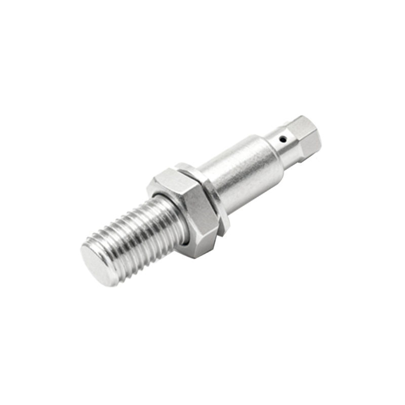
Now, let's understand the working principle. The concept is straightforward: the IR LED constantly emits an invisible infrared light beam. When an object comes close, this light reflects off the object and is detected by the photodiode. The photodiode converts this received light into a small electrical current. This tiny current change is too weak to trigger an output directly. This is where the op-amp becomes crucial. Configured as a comparator, the LM358 amplifies this small signal. When the reflected light exceeds a certain threshold (meaning an object is near), the op-amp's output switches, lighting up our indicator LED.
Time to build the circuit. First, place the LM358 op-amp chip across the center gap of your breadboard. Connect pin 8 (VCC) to the positive rail and pin 4 (GND) to the negative rail. For the transmitter side, connect the anode (longer leg) of the IR LED to the positive rail through the 220-ohm resistor (this limits current to protect the LED). Connect its cathode to the negative rail. For the receiver, connect the photodiode's cathode (often the shorter leg or marked side) to the positive rail. Connect its anode to one end of the 10k-ohm resistor. Connect the other end of this 10k resistor to the negative rail. This point, between the photodiode anode and the 10k resistor, is your signal. Connect this point to the non-inverting input (pin 3) of the op-amp.
Next, we need to set a reference voltage. Create a voltage divider using two 10k resistors in series between the positive and negative rails. Connect the midpoint between these two resistors to the inverting input (pin 2) of the op-amp. This sets a baseline comparison level. Finally, for the output, connect pin 1 of the op-amp to the anode of a regular LED. Connect the cathode of this LED to the negative rail through a 220-ohm resistor. Double-check all connections against a standard IR proximity sensor schematic before powering the circuit.
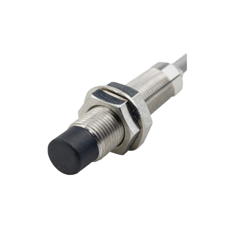
Once you carefully apply power, the IR LED should be active (you can check it with a smartphone camera, which often sees IR light as a purple glow). The output LED should remain off. Now, bring your hand or a sheet of paper close to the IR LED and photodiode, which should be placed side-by-side. As your hand approaches, the output LED should light up! Move your hand away, and it should turn off. You have successfully created a basic proximity detector.
You might need to adjust the sensitivity. The detection range is influenced by the strength of the IR emission and the ambient light. Try experimenting. Cover the sensor area from bright room light to see if performance improves. Adjust the distance between the IR pair and the object. You can also try replacing the fixed voltage divider on pin 2 with a potentiometer to dynamically change the reference voltage and fine-tune the sensing threshold. This is how engineers calibrate sensors for different environments.
This simple experiment demystifies a key technology. The core takeaway is the "emit and reflect" principle used in many IR-based sensors. From this basic setup, one can imagine more advanced applications: replacing the output LED with a relay to control a motor or a door lock, integrating the signal into an Arduino for digital processing, or using modulated IR signals to avoid interference from ambient light—a technique used in TV remotes. The journey from this breadboard to the sophisticated sensors in your smartphone is one of refinement and integration, but the fundamental idea remains beautifully simple. So, grab your components and start exploring the invisible world of light-based sensing.
SEO