In industrial automation, proximity sensors play a critical role in non-contact detection of objects. Among various types, fiber optic proximity sensors offer unique advantages, such as immunity to electromagnetic interference, suitability for hazardous environments, and flexibility in installation. A proper understanding of the fiber optic wiring diagram is essential for ensuring reliable operation and system integration. This guide provides a comprehensive overview of typical wiring configurations, best practices, and troubleshooting tips.
Fiber optic proximity sensors consist of three main components: the amplifier unit, the fiber optic cable, and the sensing head. The amplifier, often referred to as the fiber optic amplifier or controller, processes the light signal. It typically includes LED indicators, sensitivity adjustments, and output terminals. The fiber optic cable transmits light between the amplifier and the sensing head. Depending on the model, cables may be built-in or detachable. The sensing head, placed at the detection point, emits and receives light to sense object presence.
A standard wiring diagram involves connecting the amplifier to a power supply and the load (e.g., PLC input, relay). Most amplifiers operate on DC voltages, commonly 12-24V DC. The power supply terminals are usually labeled as V+ and V- or 0V. The output can be NPN (sinking) or PNP (sourcing), corresponding to the load connection. For an NPN output, the load is connected between the output terminal and the positive supply; for a PNP output, the load is between the output and ground. Always refer to the manufacturer's datasheet for specific terminal designations.
Fiber optic cables are classified into through-beam and diffuse-reflective types. In through-beam setups, the transmitter and receiver are separate units, requiring precise alignment. The wiring diagram shows two cables: one connected to the transmitter port of the amplifier and the other to the receiver port. Diffuse-reflective types use a single cable with combined emitter and receiver fibers, simplifying installation. The amplifier's wiring remains similar, but internal circuitry differs to handle the reflected light signal.
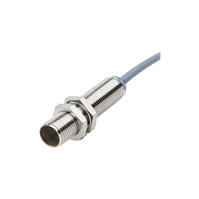
When implementing the wiring, follow these key steps: First, ensure power is disconnected to prevent electrical hazards. Securely mount the amplifier in a control panel, avoiding areas with excessive vibration or heat. Route fiber optic cables carefully, maintaining bend radii above the specified minimum (usually 20-30 mm) to prevent signal loss. Use cable glands or strain relief fittings at entry points to protect the delicate fibers. Connect the power supply wires according to polarity, and verify the voltage matches the amplifier rating. Attach the load to the output terminal, considering the current capacity (often 100 mA max). Finally, connect the fiber optic cable to the amplifier's port, ensuring it clicks into place.
After wiring, perform calibration and testing. Power on the system and observe the amplifier's indicators. Most units have a green power LED and a red/orange detection LED. Adjust the sensitivity potentiometer until the detection LED responds appropriately to the target object. Use the teach function if available for automatic threshold setting. Test with actual objects to confirm stable operation across expected conditions.
Common issues include no output, unstable detection, or short sensor life. For no output, check power connections, fuse status, and output wiring. Ensure the load impedance is within limits. Unstable detection often results from improper sensitivity setting, dirty sensing heads, or ambient light interference. Clean the fiber tip with isopropyl alcohol and adjust sensitivity. For environments with strong ambient light, use models with modulated light sources. Short cable life may stem from excessive bending or mechanical stress—review installation practices.
Advanced applications may involve multiple sensors connected to a network or programmable logic controller (PLC). In such cases, each amplifier's output is wired to a separate PLC input. Some amplifiers offer analog outputs or IO-Link communication for enhanced diagnostics and parameter setting. Always adhere to local electrical codes and safety standards, such as NEC, IEC, or ISO directives, particularly in explosive atmospheres where intrinsically safe designs are required.
Regular maintenance ensures long-term reliability. Periodically inspect cables for damage, clean sensing heads, and verify electrical connections. Log performance data to identify trends or degradation. With correct wiring and upkeep, fiber optic proximity sensors provide precise, durable detection for demanding industrial automation tasks.