Proximity sensors are critical components in modern industrial automation, providing non-contact detection of metallic and non-metallic objects. Proper leveling and alignment of these sensors are essential for ensuring accurate, reliable, and repeatable operation. Incorrect installation can lead to false triggers, reduced sensing ranges, or complete system failure, impacting productivity and safety. This article details professional techniques for achieving optimal proximity sensor leveling in various industrial environments.
The foundation of successful sensor leveling begins with understanding the sensor's operating principle. Inductive proximity sensors generate an electromagnetic field to detect metallic targets, while capacitive types detect changes in capacitance for both metallic and non-metallic materials. Photoelectric sensors use light beams. Each type has a specific sensing field geometry—typically conical or cylindrical—which dictates the optimal approach for alignment relative to the target. Always consult the manufacturer's datasheet for the precise effective sensing area and recommended installation clearances.
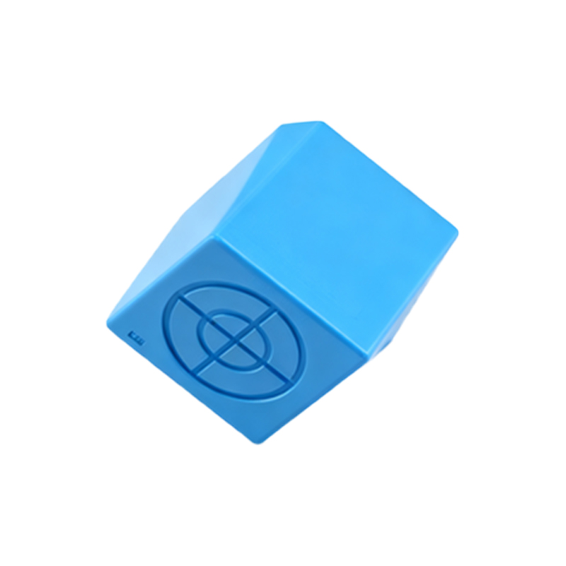
Pre-installation preparation is paramount. Ensure the mounting location is clean, stable, and free from excessive vibration. Identify the target object's material, size, shape, and expected approach path. For standard applications, the sensor should be mounted so that the target approaches perpendicular to the sensing face. This maximizes the interaction with the sensor's field. Use high-quality mounting brackets designed for the specific sensor model to provide rigid support and fine adjustment capability.
The core leveling process involves mechanical alignment and electrical verification. Mechanically, use a precision level or dial indicator to align the sensor's sensing face parallel to the target surface. Even a slight angular misalignment can significantly reduce the effective sensing distance. For cylindrical barrel sensors, ensure the central axis is perpendicular to the target path. After rough alignment, secure the sensor in its bracket but leave the fasteners slightly loose for final micro-adjustments.
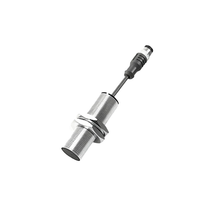
Electrical verification is the next critical step. Connect the sensor to its power supply and monitoring device, such as a programmable logic controller (PLC) input or a pilot lamp. Introduce the target object into the sensing zone along the normal operating path. Observe the sensor's response. Using the monitoring tool, measure the precise point of switch activation (the "operating point") and release (the "release point"). The difference between these points is the hysteresis, which should be within the datasheet specifications. If the switch point is inconsistent or occurs outside the expected range, mechanical re-alignment is necessary.
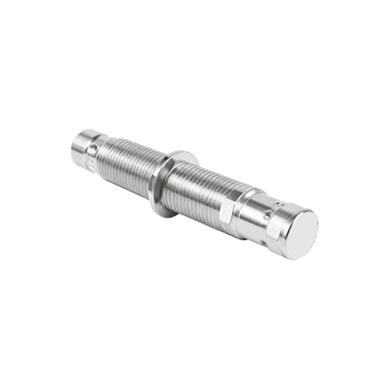
For applications requiring extreme precision, such as part positioning on a conveyor or edge detection in cutting machinery, employ a setup with micrometer-adjustable mounts. Slowly move the target into position while monitoring the output signal with an oscilloscope or a high-speed PLC input module. Adjust the sensor's position in minute increments until the trigger point is exactly at the desired location. Lock the adjustment screws securely, applying thread-locking compound if exposed to vibration. Re-test the activation point several times to confirm stability.
Environmental factors heavily influence leveling integrity. Temperature fluctuations can cause thermal expansion in mounting structures, shifting alignment over time. In such environments, consider sensors with temperature compensation and perform periodic re-verification. Strong electromagnetic interference (EMI) from nearby motors or welders can affect inductive sensors. Ensure proper shielding and maintain adequate distance from EMI sources. For applications with multiple sensors, prevent mutual interference by maintaining the minimum separation distance specified by the manufacturer, often 1.5 to 2 times the sensor diameter.
Maintenance and periodic re-calibration are part of a robust leveling strategy. Establish a schedule to check sensor alignment, looking for physical damage, loose mounts, or buildup of contaminants like oil, dust, or metal chips on the sensing face. Clean the face with a soft cloth and isopropyl alcohol if needed. Re-verify the operating point annually or during scheduled machine overhaul. Document all alignment settings and calibration results for traceability.
In summary, achieving and maintaining precise proximity sensor leveling is a systematic process combining mechanical precision, electrical verification, and environmental awareness. By adhering to these techniques, engineers can maximize sensor lifespan, ensure process reliability, and minimize costly downtime in automated industrial systems.