In the realm of industrial automation and electronic control systems, proximity sensors are indispensable components. They detect the presence or absence of an object without physical contact, making them crucial for applications ranging from assembly lines to safety interlocks. For electrical engineers and designers, accurately representing these sensors in circuit diagrams, or schematics, is fundamental for clear communication, correct implementation, and effective troubleshooting. This guide outlines the standard practices and considerations for drawing proximity sensors in your electrical schematics.
First and foremost, understanding the sensor type is essential before placing any symbol. Proximity sensors are broadly categorized by their sensing technology and output type. The most common technologies include Inductive (for detecting metallic objects), Capacitive (for detecting both metallic and non-metallic objects), and Ultrasonic or Photoelectric (often for longer ranges). Each type functions differently, but their schematic representation primarily hinges on their electrical output and connection requirements.
The core of schematic representation is the graphical symbol. While standards like IEC 60617 and ANSI/IEEE Std 315 provide guidelines, practical industry schematics often use simplified, functional symbols. A typical proximity sensor symbol resembles a standard switch symbol but is encapsulated within a circle or a square, often with a distinctive marking to indicate its non-contact nature. A common representation for a generic proximity sensor is a diamond shape or two concentric circles with a sensing field indicated by dashed lines. However, the most critical element is not the icon itself but the accompanying designators and annotations.
The output configuration dictates the wiring and thus the symbol's connection points. The three primary output types are:
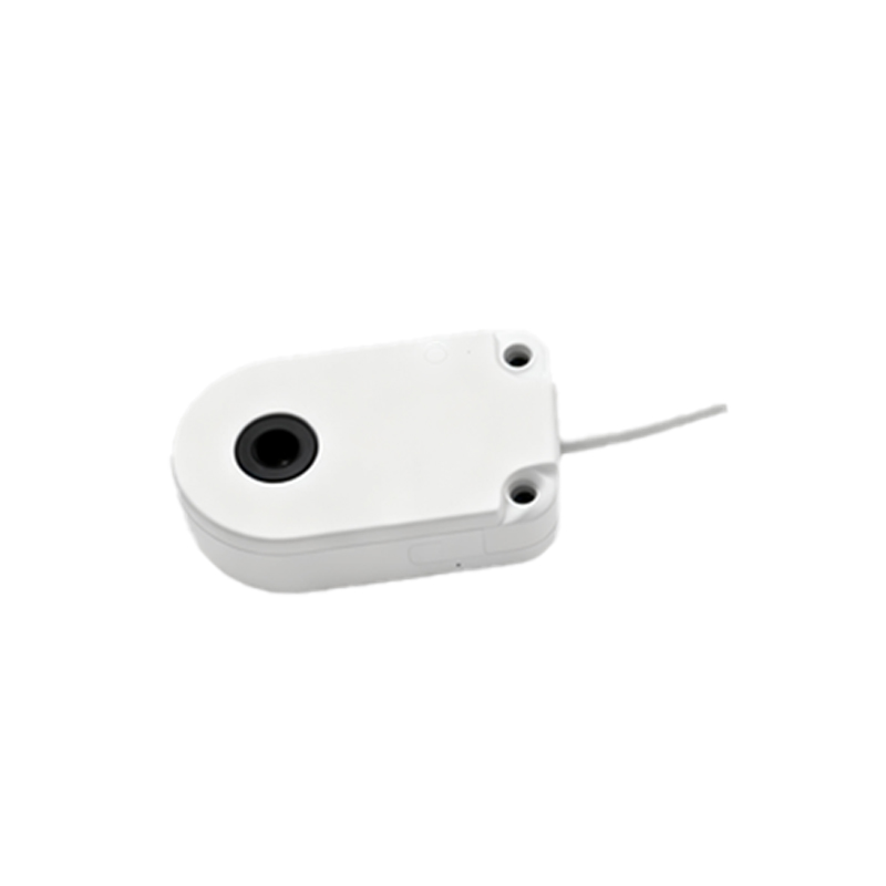
1. PNP (Sourcing): The sensor switches the positive voltage line to the load. In schematics, the symbol will show the load connected between the sensor's output wire and the common negative (0V).
2. NPN (Sinking): The sensor switches the negative or ground line to the load. Here, the load is connected between the positive supply and the sensor's output wire.
3. Analog or IO-Link: These provide a continuous signal (e.g., 4-20mA, 0-10V) or digital communication. They are represented similarly to digital sensors but with notations like "Analog Out" or specific designators for communication wires (e.g., C/Q, L+).
A proper schematic entry must include clear designators and labels. The sensor should have a unique reference designator, typically following the format "B" for sensors (as per IEC 61346) or "PRX" for proximity in many industrial drawings (e.g., PRX1, PRX2). Next to the symbol, a text note is vital. This note should specify:
Type: e.g., Inductive, Capacitive.
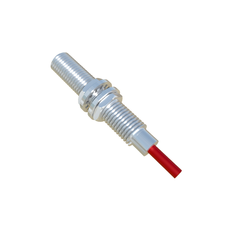
Output: e.g., PNP NO (Normally Open), NPN NC (Normally Closed), Analog.
Rating: Supply voltage (e.g., 10-30V DC) and current rating.
Part Number (Optional but recommended): For detailed BOM integration.
The power supply connections must be explicitly shown. A standard 3-wire DC sensor requires connections for Supply Positive (+V, often 24V DC), Supply Negative (0V or Common), and the Output Signal. These wires should be drawn connecting to the appropriate power rails and the input module of a PLC (Programmable Logic Controller) or the subsequent control device. For a 2-wire AC sensor, it is wired in series with the load and the AC supply, similar to a mechanical switch. Always indicate wire numbers or terminal designations (e.g., +V: Pin 1, Output: Pin 2, 0V: Pin 3) on the connecting lines.
Consider the sensor's role in the control circuit. Is it a limit switch initiating a motor start? A safety device halting a machine? This context influences how you draw the surrounding logic. The output of the proximity sensor usually feeds into a PLC input module. Therefore, the schematic should clearly show the sensor's output wire terminating at a specific PLC input point (e.g., I0.0), with the common wire completing the circuit to the PLC's common terminal. For complex systems, a separate I/O drawing listing all sensor connections to the PLC is standard practice.
Finally, consistency and adherence to your company's or project's drafting standards are paramount. Whether you use a detailed symbol from an official library or a simple switch-like symbol with a "PRX" label, maintain the same convention throughout the entire set of drawings. This ensures that anyone reading the schematic—from the designer to the field technician—can instantly recognize and understand the function and wiring of every proximity sensor in the system. Remember, a well-drawn schematic is not just a