Inductive proximity sensors are fundamental components in modern industrial automation, offering non-contact detection of metallic objects. Their robust design, reliability, and ability to function in harsh environments make them indispensable in applications ranging from assembly lines to machinery safety systems. This article delves into the core operating principles of these sensors, explaining the underlying physics and typical implementation considerations.
At the heart of an inductive proximity sensor lies a coil wound around a ferrite core, which forms part of an oscillator circuit. When energized, this oscillator generates a high-frequency electromagnetic field that radiates from the sensor's active face. In the absence of a metallic target within its sensing range, the oscillator operates at a stable, predefined amplitude. This state corresponds to the sensor's normal or "off" output condition, depending on its configuration (normally open or normally closed).
The fundamental detection principle is based on electromagnetic induction and eddy current generation. When a conductive metal object enters the oscillating electromagnetic field, eddy currents are induced on the surface of the target material. These circulating currents, governed by Lenz's Law, create their own magnetic field that opposes the original field generated by the sensor's coil. This opposition results in a loss of energy within the oscillator circuit, manifesting as a reduction in the amplitude of the oscillations.
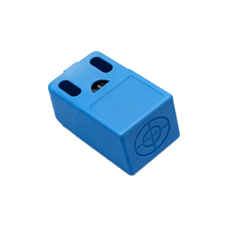
A threshold circuit within the sensor continuously monitors this amplitude. Once the amplitude drops below a specific threshold—indicating the presence of a target within the nominal sensing distance—the sensor's output state switches. This switch triggers a solid-state output (typically NPN or PNP transistor) or, in some models, a relay contact, sending a signal to the connected control system like a PLC (Programmable Logic Controller). The target can then move away, allowing the oscillation amplitude to recover and reset the output to its original state.
Several key factors influence the performance and sensing distance (Sn) of an inductive sensor. The most significant is the target material's properties. Ferrous metals (like mild steel) cause the greatest amplitude damping due to both eddy current losses and additional magnetic hysteresis losses, resulting in the standard sensing distance. Non-ferrous metals (like aluminum, brass, or copper) generate eddy currents but lack the magnetic permeability of steel, typically yielding a reduced sensing range, often 40-60% of the standard Sn. Stainless steel's response varies by grade but generally falls between these two categories.
The target's size and shape also play a crucial role. For optimal performance, the target should be at least equivalent to the sensor's active face diameter. Smaller targets or thin foils may not induce sufficient eddy currents for reliable detection, requiring a reduced operating distance. Standardized testing uses a square mild steel target of defined thickness (usually 1mm) with a side length equal to the sensor's diameter or three times the rated sensing distance, whichever is greater.
Other practical considerations include the installation environment. Inductive sensors are inherently immune to non-metallic substances like dust, oil, or water, making them ideal for dirty conditions. However, mounting them adjacent to each other or near large metal structures (like machine frames) can cause mutual interference or a reduction in the effective sensing distance due to magnetic field interaction. Manufacturers specify minimum lateral and flush-mounting distances to mitigate this. Temperature fluctuations can also affect the oscillator's characteristics, so sensors are designed with compensation circuits to maintain stability over their specified operating temperature range.
Modern advancements have led to specialized variants. Factor-1 sensors are designed to detect all metals at approximately the same range, simplifying application where target material varies. Weld-field immune sensors incorporate special shielding to resist interference from strong magnetic fields generated during resistance welding processes. Analog output sensors provide a continuous signal (e.g., 4-20mA or 0-10V) proportional to the target distance, enabling applications in positioning or thickness measurement.
In summary, inductive proximity sensors operate on a well-defined electromagnetic principle. By generating a high-frequency field and detecting the eddy current losses caused by metallic objects, they provide a robust, wear-free solution for position sensing. Understanding the interplay between the oscillator, target material, geometry, and environment is essential for selecting and applying these sensors effectively in complex industrial systems, ensuring reliable operation and maximizing system uptime.