In the realm of industrial automation, the precise and reliable operation of proximity and photoelectric sensors is paramount. These devices, the silent sentinels of modern manufacturing, are responsible for detecting the presence, absence, or position of objects without physical contact. However, their efficacy is not solely determined by their intrinsic specifications; their physical placement is a critical, often underestimated, factor that directly impacts system performance, longevity, and safety. This article delves into the key principles and practical considerations for the optimal installation of these sensors.
The first and foremost consideration is the Sensing Range and Field of View. Every sensor has a specified nominal sensing distance. Installation must account for this range, ensuring the target object reliably enters the detection zone. For inductive proximity sensors (detecting metals), the sensing distance can be affected by the target material's type and size. Capacitive sensors (detecting various materials) are sensitive to environmental factors like humidity. Photoelectric sensors, with their beams of light, require a clear line ofsight. Retro-reflective models need precise alignment with their reflector; through-beam sensors demand accurate alignment between emitter and receiver. A common mistake is installing a sensor at its maximum rated distance, leaving no margin for mechanical vibration, thermal expansion, or target positioning tolerances. A best practice is to utilize 50-80% of the nominal range to ensure a robust signal margin.
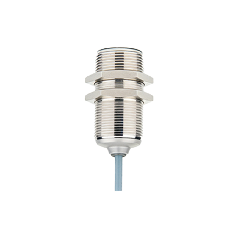
Environmental Factors constitute the second major pillar of placement strategy. Industrial environments are harsh. Consider the following:
Physical Obstructions and Debris: Sensors should be positioned away from paths where flying chips, coolant splash, or accumulating dust and grime are prevalent. For photoelectric sensors, a dirty lens drastically reduces performance. Using protective shrouds or choosing sensors with built-in air-blast cleaning ports can be beneficial.
Ambient Light: Photoelectric sensors, especially diffuse models, can be blinded or triggered by strong ambient light from welding arcs, furnace openings, or sunlight. Positioning the sensor so that external light sources do not shine directly into the receiver is crucial. Selecting sensors with modulated LED light (typically invisible infrared) and dedicated synchronous detection circuits mitigates this issue.
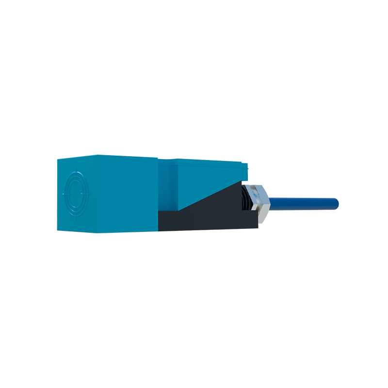
Electromagnetic Interference (EMI): High-voltage cables, motor drives, and welding equipment generate significant EMI. Avoid routing sensor cables in parallel with power cables in the same conduit or cable tray. Maintain a minimum separation distance (e.g., 30 cm). Using shielded cables and properly grounding the shield at the controller end, not the sensor end, is essential.
Temperature and Vibration: Install sensors away from extreme heat sources like ovens or exhausts, respecting their operating temperature specifications. Vibration can loosen mounting hardware and misalign sensitive optics. Use locking nuts, thread-locking compounds, and robust mounting brackets. Vibration-dampening mounts may be necessary in high-vibration areas.
The Mechanical Integration and Target Characteristics demand careful analysis.
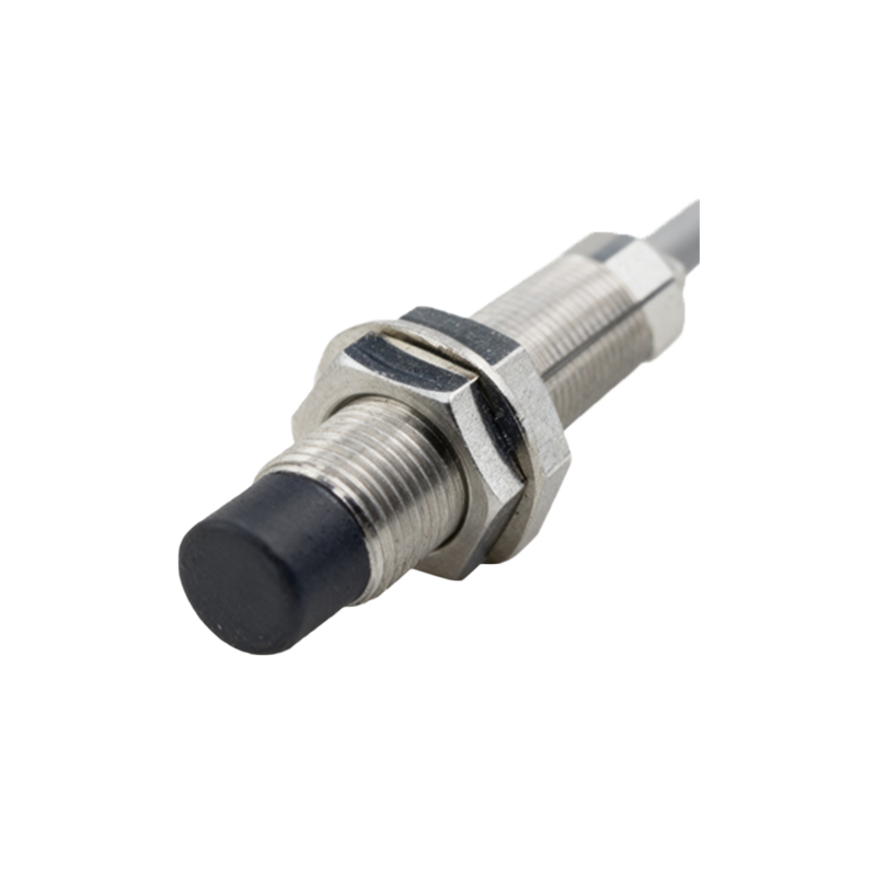
Target Size, Material, and Approach Angle: The effective sensing point can shift with a very small target. Ensure the target is large enough to reliably interrupt or reflect the sensing field. For proximity sensors, the standard target is a square of mild steel. For non-ferrous metals, the sensing distance reduces, requiring closer installation. The optimal approach for a proximity sensor is head-on. Avoid tangential approaches which reduce the effective sensing area.
Mounting Stability: The sensor's mounting must be rigid. Any flex or movement in the bracket will cause false triggers. Use sturdy metal brackets instead of plastic where possible. For cylindrical sensors, correct mounting nuts should be used to prevent rotation.
Accessibility for Maintenance: Sensors will eventually require cleaning, realignment, or replacement. Position them where technicians can safely and easily access them without dismantling major machine components. This reduces downtime during troubleshooting and preventive maintenance.
Electrical and Wiring Considerations are often an afterthought but are vital. Ensure the cable is not taut, leaving slack for minor adjustments and strain relief. Use flexible conduit or cable carriers in areas with moving parts. Protect cables from sharp edges, abrasion, and pinch points. Adhere to the manufacturer's guidelines for wiring, particularly for sensors with programmable functions or IO-Link communication, ensuring correct pinouts and cable types.
Finally, a Systematic Verification and Documentation process seals the installation. After placement, systematically test the sensor with the target under all expected operating conditions—different speeds, temperatures, and lighting states. Use the sensor's indicator LED or a monitoring tool to verify a strong, consistent signal. Document the installation location, sensor type, part number, and alignment specifics in machine manuals. This is invaluable for future maintenance and troubleshooting.
In conclusion, the installation of proximity and photoelectric sensors is a discipline that blends electrical knowledge with mechanical insight. By meticulously considering the sensing