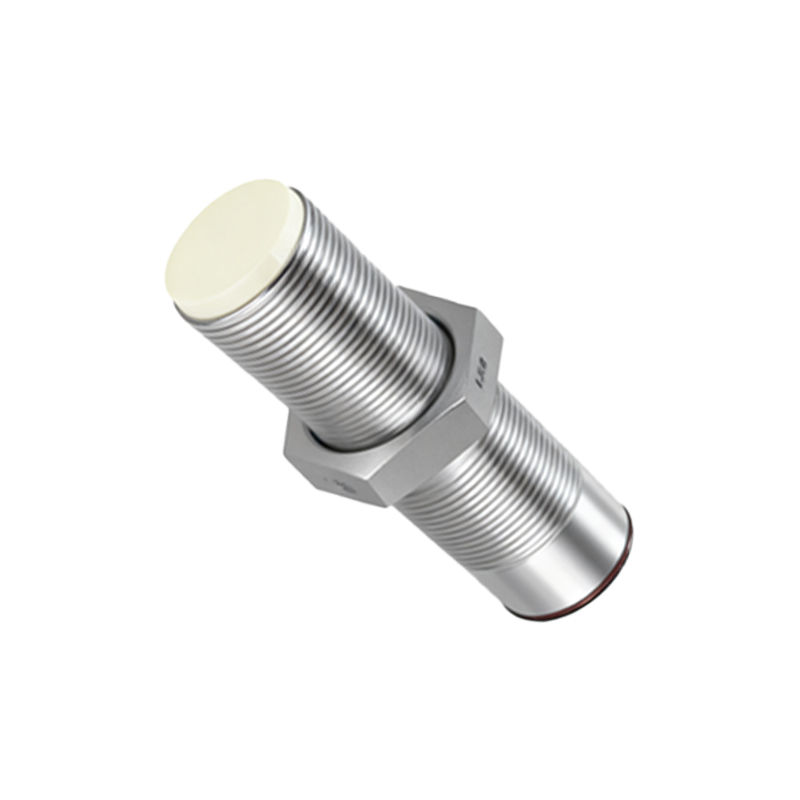
In the world of industrial automation and electronic design, PNP proximity sensors are ubiquitous components. While technical datasheets provide specifications, high-quality PNP proximity sensor images serve as a crucial visual bridge, offering immediate understanding of form factors, mounting styles, wiring configurations, and real-world integration. This guide delves into the significance of these images and how to interpret them effectively.
A PNP proximity sensor is a type of solid-state switching device that detects the presence of a metallic or sometimes non-metallic target without physical contact. The "PNP" designation refers to the transistor output type, meaning the sensor's output wire switches to a positive voltage when an object is detected. Visually distinguishing a PNP sensor from its NPN counterpart is often the first challenge, and this is where clear product images are invaluable. High-resolution photographs typically show the sensor body, which can be cylindrical (e.g., M8, M12, M18, M30 threaded barrels), rectangular, or block-shaped. Key details visible in a good image include the sensing face, LED indicator lights (usually for power and output status), and the cable or connector type.
Perhaps the most critical image for engineers and technicians is the wiring diagram. A standard PNP proximity sensor image depicting wiring will show three wires: brown (typically for DC positive/V+), blue (for DC negative/0V or common), and black (the switched PNP output). The diagram illustrates that when a target is detected, the black wire connects internally to the positive supply (brown wire), providing a signal to the load (like a PLC input). Comparing this visual schematic to an NPN diagram, where the output switches to negative, clarifies a fundamental difference in circuit design. Many installation guides use annotated images to show the correct connection to programmable logic controllers (PLCs), emphasizing that a PNP sensor's output is best suited for sinking PLC input modules.
Beyond basic identification, application photos are immensely helpful. These images showcase PNP sensors in situ—mounted on a machine frame to detect a passing gear tooth, positioned alongside a conveyor belt to count packages, or integrated into a robotic gripper to confirm part presence. Such context reveals practical aspects like required mounting brackets, necessary sensing distance (highlighted in cutaway diagrams), and environmental considerations (with images of sensors featuring IP67 or IP68 ratings for dust and water resistance). For instance, an image of a cylindrical PNP inductive sensor installed in a metal bracket will often include a note on maintaining a non-ferrous surround to ensure the specified sensing range is achieved.
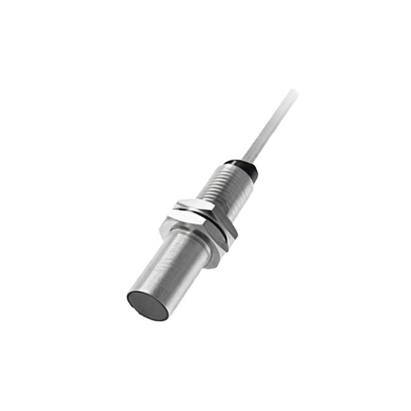
When searching for or evaluating PNP proximity sensor images, look for clarity and technical detail. Useful images often include scale, either through a common object like a coin or with dimension callouts. Cross-sectional views or animated GIFs can demystify the internal operation, showing the oscillator, trigger circuit, and output switching transistor. For those involved in procurement, images displaying packaging, labeling, and connector options (like quick-disconnect M12 connectors) streamline the selection process.
In conclusion, PNP proximity sensor images are far more than just product pictures. They are essential educational and specification tools. From a clear wiring schematic that prevents installation errors to an application photo that sparks a design solution, these visuals translate complex electronic functionality into actionable information. Whether you are a student, a maintenance technician, or a design engineer, learning to read and utilize these images effectively is a key skill in mastering sensor technology and ensuring reliable automation system performance. Always refer to the manufacturer's official documentation, where images and diagrams are most accurate, to complement your understanding gained from these visual resources.