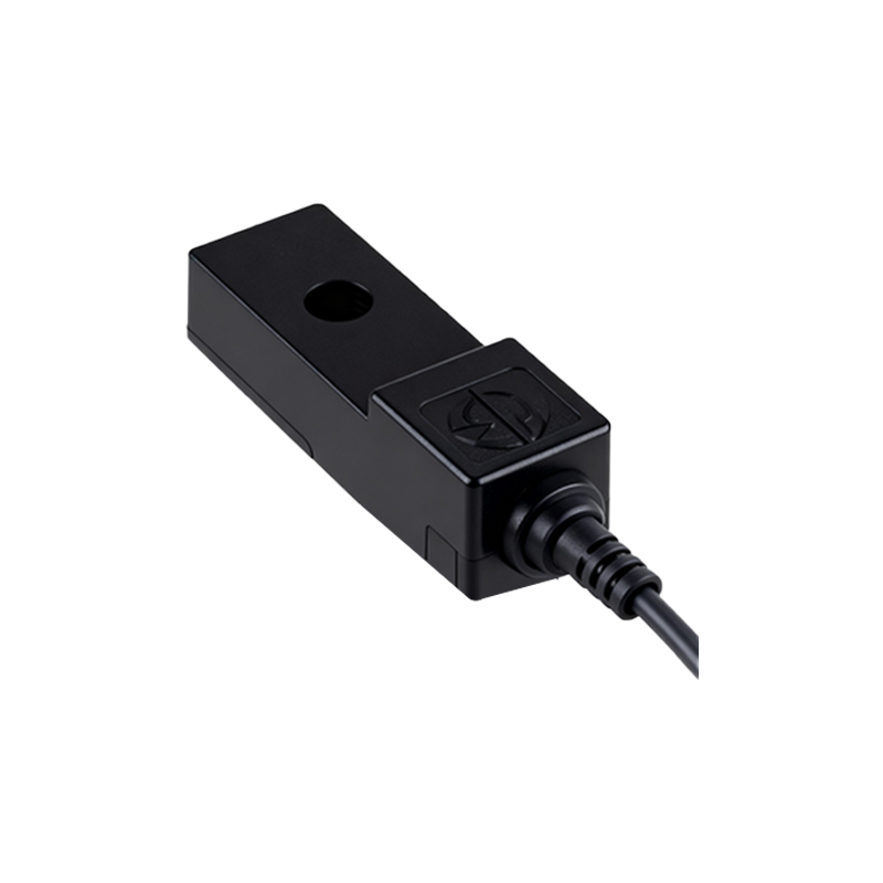
Understanding the pinout of a proximity sensor is essential for proper installation and reliable operation in industrial automation, robotics, and consumer electronics. These non-contact sensors detect the presence or absence of an object within a specified range, and their functionality hinges on correct electrical connections. While specific pin configurations vary by model and type (inductive, capacitive, or photoelectric), most proximity sensors share common wiring principles.
Typically, a standard 3-wire DC proximity sensor features three distinct pins: brown, blue, and black. The brown wire is universally designated for the positive supply voltage, usually ranging from 10 to 30 VDC. The blue wire connects to the ground or negative terminal of the power supply, completing the circuit. The black wire serves as the output signal line. When the sensor detects a target, it switches this output line, either sourcing or sinking current to interface with a programmable logic controller (PLC), relay, or other control devices. It is critical to verify the sensor's output type—NPN (sinking) or PNP (sourcing)—to match the input requirements of the connected controller. Miswiring can lead to sensor failure or damage to the control system.
For 4-wire proximity sensors, an additional wire, often white or gray, provides a second output channel, enabling configurations like normally open (NO) and normally closed (NC) signals from the same unit. Some advanced models may include pins for diagnostic functions, such as short-circuit protection or output status indicators. Always refer to the manufacturer's datasheet for the exact pin definitions, as color codes or functions can differ, especially in AC-powered sensors or specialized variants.
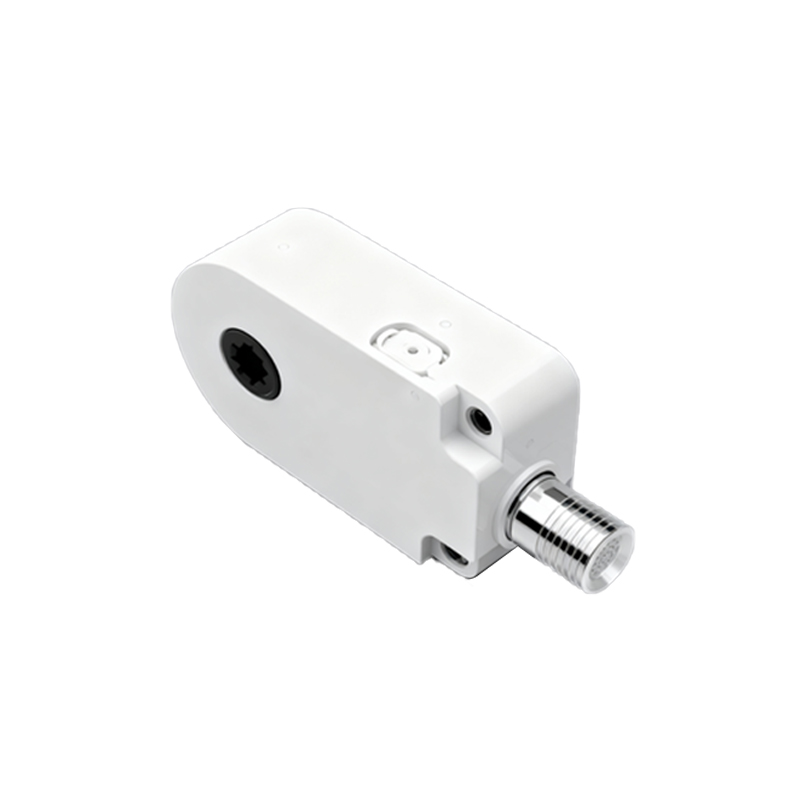
Proper wiring practices are paramount. Ensure power is disconnected during installation. Use shielded cables in electrically noisy environments to prevent false triggering. Maintain the recommended operating voltage and current limits to avoid overheating. Secure connections with appropriate terminals, and avoid placing signal wires parallel to high-voltage lines to minimize interference. For long-distance wiring, consider voltage drop and use thicker gauge wires if necessary.
Testing the sensor after installation confirms correct operation. Apply power and observe the output indicator LED, if present. Use a multimeter to check the voltage on the output pin when a target is presented and removed. The sensor should respond within its specified switching frequency. Regular maintenance, including cleaning the sensing face and checking for loose connections, prolongs sensor life.
In summary, mastering proximity sensor pinouts involves identifying power, ground, and output pins while adhering to wiring standards. This knowledge ensures seamless integration into control systems, enhancing efficiency and safety in automated applications. Always prioritize manufacturer guidelines and industry best practices for optimal performance.