Inductive proximity sensors are a cornerstone of modern industrial automation, offering non-contact detection of metallic objects. Among the various output configurations, the PNP type is widely prevalent, particularly in European and Asian markets. This article delves into the specifics of PNP inductive proximity sensors, explaining their operation, wiring, and key application areas, providing a clear guide for engineers and technicians.
At its core, an inductive proximity sensor generates an electromagnetic field via a coiled oscillator circuit located at its sensing face. When a metallic target enters this field, eddy currents are induced within the target. This causes a load on the oscillator, leading to a change in its amplitude. This change is detected by the sensor's circuitry, which then triggers a change in the output state.
The critical distinction lies in the output switching logic. A PNP inductive proximity sensor is characterized by its "sourcing" output. In its normal state (no target present), the output signal wire is disconnected from the positive supply voltage (typically +24V DC). When a target is detected, the sensor's internal electronic switch closes, connecting the output signal wire directly to the positive supply voltage (+V). This means it "sources" positive current to the load. The load (e.g., a PLC input, relay coil, or indicator light) is connected between the sensor's output signal wire and the common negative (0V) of the power supply.
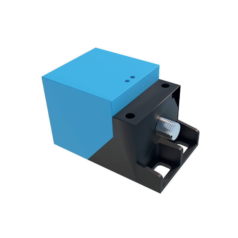
A simple wiring example clarifies this. For a 3-wire DC PNP sensor, you connect the brown wire to +24V DC, the blue wire to 0V DC (common). The black (or sometimes white) wire is the output signal. When activated, this black wire will supply +24V. The load is connected between this black wire and the 0V (blue wire) line. This is often summarized as: PNP = Positive-switched, meaning the switched output is the Positive voltage.
Contrasting this with the NPN type is essential. An NPN sensor is a "sinking" output. When active, it connects the output signal wire to the negative (0V) rail, "sinking" current from the load to ground. The choice between PNP and NPN often depends on regional conventions and the specific requirements of the control system's input card. Many modern PLCs can accept both types, but understanding the difference prevents wiring errors.

The advantages of PNP inductive proximity sensors are significant. Their solid-state design ensures a long operational life with no moving parts to wear out. They are highly reliable in harsh industrial environments, resistant to dust, moisture, and vibrations. The non-contact nature eliminates mechanical wear on both the sensor and the target, allowing for high-speed operation and millions of cycles. Their primary limitation is that they only detect metals, with sensing ranges varying based on the target's material (ferrous metals like steel are detected at the nominal range, while non-ferrous metals like aluminum or copper have a reduced range).
Typical applications for PNP inductive proximity sensors are vast across factory floors. They are extensively used for position sensing, such as detecting the presence or absence of a metal part on a conveyor, verifying if a cylinder is in the retracted or extended position, or counting metallic objects. They serve as end-of-travel limit switches in automated machinery without the physical contact of mechanical levers. In rotary systems, they can detect the teeth of a gear for speed monitoring. They are also fundamental in safety interlock systems, confirming that a metal guard door is securely closed before machine operation can commence.
When selecting a PNP inductive proximity sensor, key specifications must be considered. The sensing distance, or nominal range (Sn), is crucial and should be derated for non-ferrous targets. The housing material (e.g., stainless steel, nickel-plated brass, or PBT plastic) must suit the environment—whether it's washdown, oily, or exposed to chemicals. The electrical specifications, including operating voltage range, output current capacity, and switching frequency, must match the control system. Additionally, the output configuration, whether normally open (NO) or normally closed (NC), defines the logic of the signal upon detection.
Installation requires attention to detail. Sensors should be mounted securely to minimize vibration. It is vital to maintain a clearance zone around the sensor's sensing face, as specified by the manufacturer, to prevent interference from surrounding metal (the "flush-mountable" or "non-flush" designation indicates this capability). Proper shielding of cables in electrically noisy environments is recommended to prevent false triggering.
In summary, the PNP inductive proximity sensor is a versatile, robust, and essential component in automation. Its sourcing output logic provides a straightforward interface with many control systems. By understanding its working principle—from the electromagnetic field generation to the sourcing PNP switch—and its correct wiring methodology