Proximity sensors are indispensable components in modern automation, manufacturing, and countless electronic devices. They detect the presence or absence of an object without physical contact, using electromagnetic fields, light, or sound. Ensuring these sensors function correctly is critical for system integrity, safety, and efficiency. This guide outlines a systematic, practical approach to testing proximity sensors, helping technicians and engineers verify performance and diagnose common issues.
Before initiating any tests, safety is paramount. Always disconnect power to the sensor and the associated machinery whenever possible. If live testing is necessary, adhere to all lock-out/tag-out (LOTO) procedures and use appropriate personal protective equipment. Gather essential tools: a digital multimeter (DMM), an oscilloscope (for advanced signal analysis), the sensor's datasheet, a known-good target object (typically the material and size specified by the manufacturer), and a stable power supply matching the sensor's voltage requirements.
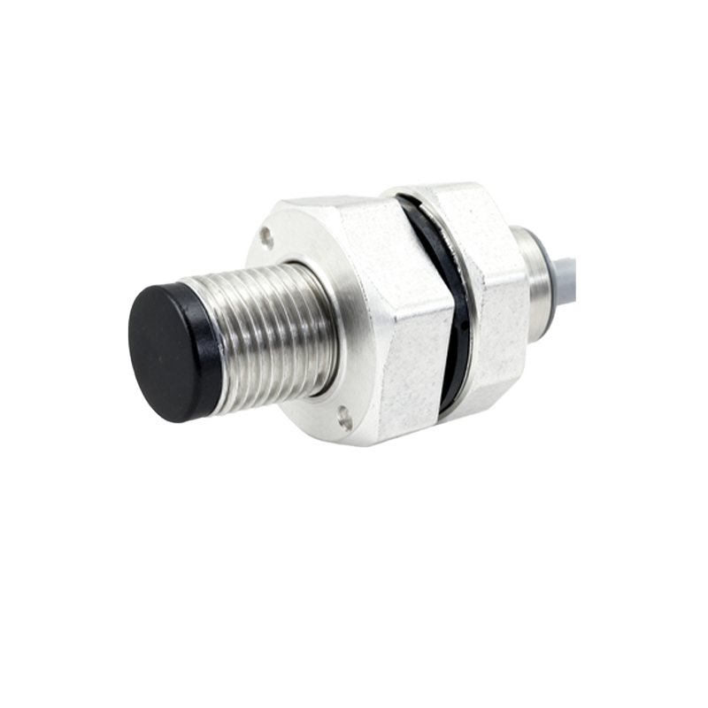
The first step is a thorough visual inspection. Check the sensor housing for cracks, dents, or signs of impact. Examine the sensing face for accumulation of dirt, metal shavings, coolant, or other contaminants that can attenuate the sensing field. Inspect the electrical connections, cable, and connector for damage, fraying, or corrosion. Even minor physical damage can significantly affect performance.
Next, verify the wiring and power supply. Using the datasheet, confirm the pin configuration (e.g., brown wire for +V, blue for 0V, black for output). With power disconnected, use the multimeter's continuity function to check for short circuits or broken wires. Reconnect power and measure the voltage at the sensor's terminals to ensure it is within the specified range (e.g., 10-30 VDC). An unstable or incorrect power supply is a frequent cause of sensor malfunction.
The core of testing involves verifying the sensor's detection capability. For this, you need the specified target. Position the target within the sensor's stated nominal sensing range. Observe the sensor's output indicator LED (if present); it should illuminate when the target is detected. The primary test is to measure the electrical output signal with your multimeter. For a standard DC sensor:
Sourcing (PNP) Sensor: Connect the multimeter's black probe to the 0V (blue) wire and the red probe to the output (black) wire. When the target is absent, the voltage should read near 0V. When the target is presented, the voltage should jump to接近 the supply voltage (e.g., 24V).
Sinking (NPN) Sensor: Connect the red probe to the +V (brown) wire and the black probe to the output (black) wire. When the target is absent, the voltage should read near the supply voltage. When the target is presented, it should drop to接近 0V.
For analog output sensors, measure the output voltage or current while varying the distance to the target. The reading should change smoothly and linearly (or according to its specified curve) as documented in the datasheet.
It is crucial to test the actual sensing distance. The datasheet provides a "nominal sensing distance (Sn)." This is not a guaranteed maximum. Factors like target material, size, and temperature affect it. To check, slowly bring the standard target axially toward the sensing face. Note the distance at which the output switches. This is the "operating point." Repeat by moving the target away to find the "release point." The difference between these points is the hysteresis, which prevents output chatter. The measured operating point should typically be between 90% and 110% of Sn under ideal conditions. A significantly reduced range indicates potential internal damage or degradation.
Environmental interference can cripple a sensor. For inductive sensors (detecting metals), ensure no other large metal objects or motors are within three times the sensor's diameter from its sides, as they can distort the magnetic field. For capacitive sensors (detecting most materials), they are susceptible to humidity, dust, and other environmental changes. Ultrasonic sensors can be affected by air turbulence, temperature gradients, and acoustic noise. Test in the actual operating environment when possible.
If the sensor fails basic tests, advanced diagnostics with an oscilloscope can reveal issues like a noisy output signal, slow switching speed, or instability that a multimeter might miss. Observe the rise and fall times of the output signal when the target is introduced and removed. Compare these to the switching frequency specifications. A slow or erratic waveform often points to internal component failure.
Common failure modes include output stuck high or low (failed output transistor), intermittent operation (loose connection or internal fault), reduced sensing range (aging oscillator components in inductive sensors), and false triggering (environmental interference or electrical noise). Methodical testing—power, wiring, output with target