Proximity sensors are indispensable components in modern industrial automation, robotics, and safety systems. Their ability to detect the presence or absence of an object without physical contact makes them reliable, durable, and versatile. For electrical engineers and technicians, understanding the schematic diagrams of these sensors is crucial for proper selection, integration, and troubleshooting. This article delves into the core principles and common schematic representations of the primary types of proximity sensors.
At its heart, a proximity sensor schematic reveals the electronic circuitry that enables non-contact detection. The fundamental principle involves generating a sensing field (electromagnetic, electrostatic, or ultrasonic) and monitoring changes in that field caused by a target object entering its range. The schematic details how this change is converted into an electrical output signal, typically a switched DC voltage or a current change.
The most common types are inductive, capacitive, and ultrasonic proximity sensors, each with distinct schematic characteristics.
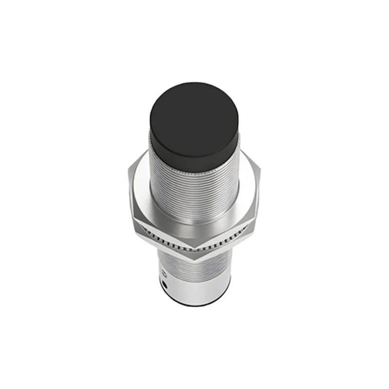
Inductive Proximity Sensors: These sensors detect metallic objects, primarily ferrous metals like iron and steel. The core of an inductive sensor is a coil (inductor) forming part of an LC oscillator circuit. In a typical schematic, you will see an oscillator block (often a Colpitts or Hartley oscillator) connected to a coil. When a metallic target enters the oscillating electromagnetic field, eddy currents are induced in the target. This causes a load on the oscillator, damping its amplitude. A subsequent threshold detector circuit (like a Schmitt trigger) senses this amplitude drop. The output of this detector then drives a switching element, usually an NPN or PNP transistor, or a solid-state relay, to provide a clean digital output signal (e.g., 0V or 24V DC). The schematic will also include components for power supply regulation, reverse polarity protection, and often a status LED indicator.
Capacitive Proximity Sensors: These can detect both metallic and non-metallic materials (plastics, wood, liquids) by sensing changes in capacitance. The schematic is conceptually similar to the inductive type but starts with a capacitor. The sensor face acts as one plate of a capacitor, with the target object acting as the other plate (or dielectric). An RC or LC oscillator circuit is used. As a target approaches, the effective capacitance changes, altering the oscillator's frequency or amplitude. This change is evaluated by a demodulator and comparator circuit. The output stage is again a transistor switch. Schematics for capacitive sensors often show a sensitivity adjustment potentiometer in the feedback loop of the oscillator or comparator, allowing calibration for different material types.
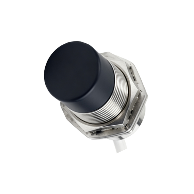
Ultrasonic Proximity Sensors: These operate on the time-of-flight principle, emitting high-frequency sound waves and listening for the echo. The schematic is more complex, divided into transmitter and receiver sections. The transmitter circuit involves an oscillator generating the ultrasonic frequency (e.g., 40 kHz), a driver amplifier, and the ultrasonic transducer (modeled as a complex capacitor/inductor combination). The receiver section features the receiving transducer, a high-gain amplifier (often multi-stage with band-pass filtering to isolate the echo frequency), and a threshold detection circuit. A microcontroller or dedicated timing IC (shown as a block in the schematic) is central, calculating the time delay between the emitted pulse and the received echo to determine distance. The output can be a simple switch, an analog voltage proportional to distance, or a digital serial signal.
Beyond the core sensing circuitry, all proximity sensor schematics share common elements. These include:
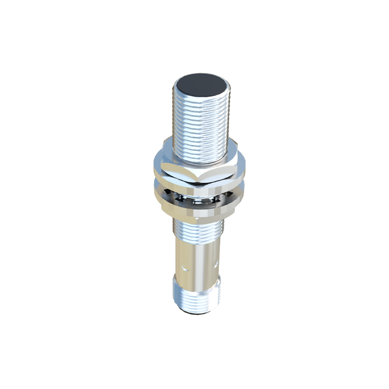
Power Supply Section: Voltage regulator (e.g., 78xx series), filtering capacitors, and protection diodes.
Output Stage: Clearly labeled as NPN (sinking) or PNP (sourcing) transistor configuration, showing the load (relay, PLC input) connection points (typically labeled V+, Output, and 0V).
Connection Diagram: A simplified representation showing the standard 3-wire or 4-wire connection (Brown/V+, Blue/0V, Black/Output, White/Secondary Output or Enable).
Reading these schematics allows engineers to: verify the sensor's compatibility with a PLC input type (sink vs. source); understand the need for an external pull-up resistor; diagnose failures by testing key voltage points; and correctly wire the sensor in series or parallel for control logic. For instance, recognizing an NPN open-collector output on a schematic immediately informs the engineer that the load must be connected between the output wire and the positive supply voltage.
In conclusion, a proximity sensor schematic is a roadmap of its functionality. By interpreting the oscillator type, detection circuit, and output configuration, electrical professionals can move beyond treating the sensor as a black box. This knowledge empowers precise application, ensures system reliability, and streamlines maintenance in complex automated environments. Always cross-reference the schematic with the manufacturer's datasheet for specific voltage