In industrial automation and control systems, proximity sensors are indispensable components for detecting the presence or absence of objects without physical contact. Among the various configurations, the 3-wire proximity sensor is one of the most common and versatile types. This guide provides a detailed, practical overview of how to correctly wire, install, and troubleshoot 3-wire DC proximity sensors, adhering to standard industry practices.
First, understanding the fundamental principle is crucial. A 3-wire DC proximity sensor typically operates on a supply voltage ranging from 10 to 30 VDC. The three wires are color-coded for identification: brown (or red) for the positive supply voltage (+V), blue (or black) for the common negative or 0V (GND), and black (or white, sometimes blue) for the output signal line. It is imperative to consult the specific sensor's datasheet, as color codes can vary by manufacturer and region (e.g., NPN vs. PNP sourcing).
The core operation revolves around the type of output transistor: NPN or PNP. This defines the sensor's "sourcing" capability.
NPN Sensors (Sinking Output): In an NPN sensor, the output transistor connects the signal wire (black) to the negative line (0V) when activated. The load (e.g., a PLC input, relay coil) must be connected between the positive supply (+V) and the sensor's output wire. When the sensor detects a target, it "sinks" the current to ground, completing the circuit and activating the load.
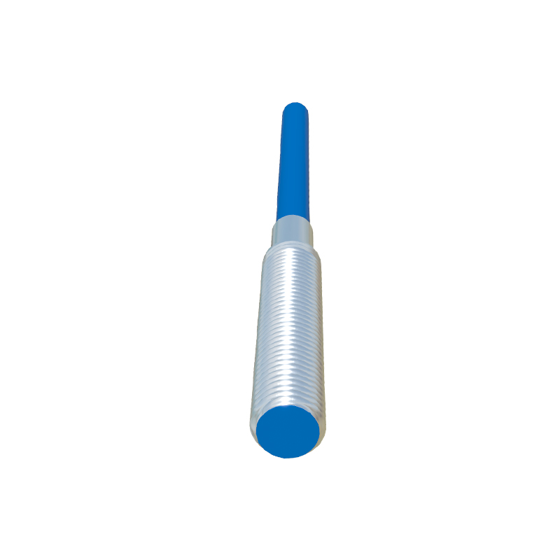
PNP Sensors (Sourcing Output): In a PNP sensor, the output transistor connects the signal wire to the positive supply line (+V) when activated. The load must be connected between the sensor's output wire and the common negative (0V). When activated, it "sources" current from the positive supply to the load.
Correct Wiring Procedure:

1. Power Supply: Ensure a stable, regulated DC power supply within the sensor's specified range (e.g., 24 VDC is industry standard). Connect the positive terminal of the power supply to the brown wire and the negative terminal to the blue wire.
2. Load Connection: This step depends on the sensor type.
For an NPN sensor: Connect one side of your load (e.g., PLC digital input module) to the positive supply rail. Connect the other side of the load to the sensor's black (output) wire.
For a PNP sensor: Connect one side of your load to the sensor's black (output) wire. Connect the other side of the load to the common negative (0V/blue wire) or power supply negative.
3. Shielding & Protection: For long cable runs or electrically noisy environments, use shielded cables and ground the shield at one end only (typically the control panel end). Always incorporate a fuse (1-2A) in the positive supply line for short-circuit protection. Transient voltage suppressors or flyback diodes (for inductive loads like relays) are highly recommended to protect the sensor's solid-state output from voltage spikes.
Installation and Configuration Tips:
Mounting: Ensure proper alignment and maintain the specified sensing distance. Metallic mounting brackets or surrounding metal can influence the sensing field; maintain the recommended non-metallic clearance.
Target Material: Inductive sensors detect metals. The sensing distance can vary based on the target's material (steel, aluminum, brass) and size. Factor in a reduction coefficient from the datasheet for non-ferrous metals.
Environment: Consider environmental factors like temperature, humidity, and the presence of cutting fluids or dust. Select sensors with appropriate IP (Ingress Protection) ratings (e.g., IP67 for washdown areas).
Indicator LED: Most sensors have an LED that illuminates when an object is detected. This is invaluable for initial setup and troubleshooting.
Common Troubleshooting Steps:
1. No Response: Verify power supply voltage at the sensor terminals. Check wiring against the datasheet diagram. Confirm the load is functional and correctly connected for the sensor type (NPN/PNP).
2. Intermittent Operation: Check for loose connections. Look for sources of electrical noise (motors, welders) and ensure proper shielding. The target might be at the edge of the sensing range; adjust positioning.
3. Sensor Stays On: Possible sensor failure or a buildup of metallic debris on the sensing face. For inductive sensors, ensure the target is moving out of the sensing field completely.
4. Short Circuit: Immediately disconnect power. Check for pinched wires or incorrect connections