In industrial automation and control systems, rectangular (or block-style) proximity sensors are indispensable components for non-contact detection of metallic or, in some cases, non-metallic objects. Their robust housing, typically in a rectangular form factor, makes them suitable for harsh environments. Correct wiring is fundamental to ensuring reliable operation, safety, and longevity. This guide provides a comprehensive, step-by-step approach to wiring a standard DC 3-wire rectangular proximity sensor, covering principles, procedures, and best practices.
First, it is crucial to understand the basic types and electrical characteristics. Rectangular proximity sensors commonly operate on DC or AC power supplies. The DC 3-wire type is the most prevalent in modern systems. These three wires are color-coded according to international standards (IEC): brown for the positive supply voltage (+V), blue for the common negative or 0V, and black for the output signal. The output can be either NPN (sinking) or PNP (sourcing). An NPN sensor switches the negative (0V) line to the load, while a PNP sensor switches the positive (+V) line. Always verify the sensor's datasheet for its specific model number, sensing distance, supply voltage range (e.g., 10-30 VDC), output type, and current rating.
Before starting any wiring work, adhere to strict safety protocols. Disconnect all power sources to the control panel or cabinet. Use a lockout/tagout (LOTO) procedure to prevent accidental re-energization. Verify the power is off using a multimeter. Gather the necessary tools: appropriate wire strippers, crimping tools, ferrules, screwdrivers, and the sensor's technical documentation.
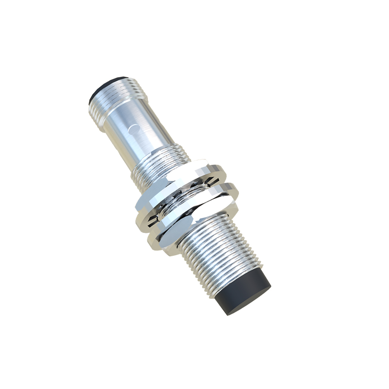
The core wiring procedure for a DC 3-wire sensor is as follows:
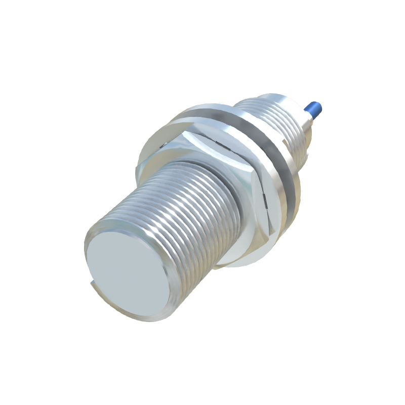
1. Power Supply Connection: Identify a suitable DC power supply within the sensor's rated voltage range. Connect the brown wire (+V) to the positive terminal of the power supply. Connect the blue wire (0V) to the negative terminal of the same power supply. This provides operating power to the sensor's internal circuitry. Ensure connections are tight and secure.
2. Output Signal Connection: The black wire is the switched output. Its destination depends on the sensor type (NPN/PNP) and the load (e.g., a PLC input module, a relay coil, or an indicator lamp).
For a PNP Sensor: The black wire provides a positive voltage when the sensor is active (target detected). Connect the black wire to one terminal of your load (e.g., PLC input channel). Connect the other terminal of the load back to the power supply's negative (0V) terminal (blue wire common). This completes the circuit.
For an NPN Sensor: The black wire provides a path to 0V (negative) when active. Connect one terminal of your load to the positive supply (+V). Connect the other terminal of the load to the black wire of the sensor. The sensor's blue wire is already connected to 0V, completing the circuit when it activates.
3. Shield Connection (if applicable): Many sensors have an additional bare or green/yellow wire for the shield. This shield wire should be connected to a functional earth (FE) or ground terminal at the control panel, not at the sensor end, to drain electrical noise and prevent interference. Leave the shield insulated and unconnected at the sensor housing.
Critical best practices must be observed for optimal performance. Always use twisted-pair or shielded cable for the sensor wires, especially in environments with significant electromagnetic interference (EMI) from motors or frequency drives. Keep sensor wiring separate from high-voltage AC power lines. Route cables neatly in cable ducts or trays. For the load, consider adding a protective element like a flyback diode across an inductive load (e.g., a relay coil) or a surge suppressor to protect the sensor's solid-state output from voltage spikes. Never exceed the sensor's maximum output current; use an intermediate relay for higher-current loads.
After wiring, perform a systematic checkout. Double-check all connections against the wiring diagram. Temporarily apply power. Observe the sensor's indicator LED (if present). Typically, a steady LED indicates power, and a blinking or brighter LED indicates target detection. Use a multimeter to measure the voltage between the black output wire and the blue wire. For a PNP sensor, it should read near the supply voltage when active and near 0V when inactive. For an NPN, it should read near 0V when active and be open-circuit (or supply voltage through the load) when inactive. Finally, conduct a functional test by introducing the target material to the sensor's sensing face at the specified distance to