In the field of electrical engineering, laser sensors play a crucial role in various applications, from industrial automation to medical devices. To effectively design, analyze, and troubleshoot circuits involving these sensors, it is essential to understand their circuit symbols. This article delves into the standard symbols used for laser sensors in schematic diagrams, explaining their components and how they integrate into broader electronic systems.
Laser sensors are typically represented in circuit diagrams by a combination of symbols that denote their functional parts. The core symbol often includes a diode symbol to indicate the laser diode, which is the heart of the sensor. This diode is usually depicted with arrows pointing outward, signifying the emission of light or laser beams. In many schematics, the laser diode symbol is enclosed within a circle or a rectangular box to represent the sensor housing, which may include additional components like lenses or detectors.
A common circuit symbol for a laser sensor consists of three main elements: the power supply connections, the laser diode, and the output signal lines. The power terminals are typically labeled as VCC (positive voltage) and GND (ground), similar to other electronic components. The laser diode is shown with an anode and cathode, where the anode is connected to the positive supply through a current-limiting resistor to prevent damage from overcurrent. The output signal, which can be analog or digital depending on the sensor type, is represented by lines extending from the sensor symbol to other parts of the circuit, such as microcontrollers or amplifiers.
In more detailed schematics, laser sensors may include symbols for photodiodes or phototransistors that detect reflected laser light. These are often drawn adjacent to the laser diode symbol, with arrows pointing inward to indicate light reception. For instance, in a triangulation laser sensor used for distance measurement, the circuit might show a laser diode emitting a beam and a photodiode array receiving the reflected light, connected to signal processing units. The symbols for these detectors follow standard conventions, with photodiodes represented as diodes with arrows pointing toward the cathode and phototransistors as transistors with light-sensitive markings.
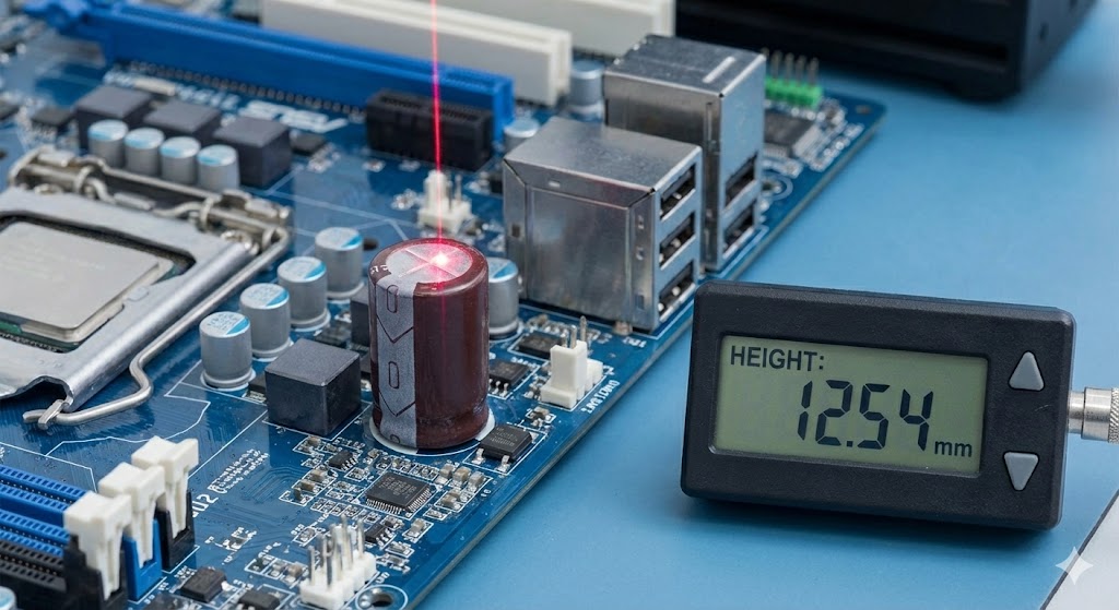
When integrating laser sensors into circuits, engineers must also consider symbols for supporting components. These include resistors for current regulation, capacitors for noise filtering, and operational amplifiers for signal conditioning. In schematic diagrams, these are connected to the laser sensor symbol via nodes and wires, forming a complete functional block. For example, a typical circuit might show a laser sensor connected to a voltage regulator IC to ensure stable power, with output signals fed into an analog-to-digital converter (ADC) for further processing.
Understanding these symbols is vital for reading datasheets and design documents. Manufacturers often provide reference schematics in datasheets, using standardized symbols per international norms like IEC (International Electrotechnical Commission) or ANSI (American National Standards Institute). These standards ensure consistency across engineering documents, reducing errors in interpretation. For laser sensors, symbols may vary slightly based on the specific type—such as continuous wave lasers versus pulsed lasers—but the fundamental elements remain similar.
In practice, laser sensor circuits can be complex, involving multiple stages like modulation drivers for pulsed operation or feedback loops for intensity control. The symbols for these advanced features might include additional annotations, such as wave shapes to denote modulation or feedback arrows. Engineers should familiarize themselves with these nuances to accurately design systems for applications like barcode scanning, LiDAR, or precision alignment.
Overall, mastering laser sensor circuit symbols enhances one's ability to work with modern electronic systems. By recognizing the standard representations and their connections, engineers can efficiently prototype, debug, and optimize circuits, ensuring reliable performance in real-world scenarios. As technology evolves, staying updated with symbol conventions in industry resources and training materials is recommended for continued professional growth.