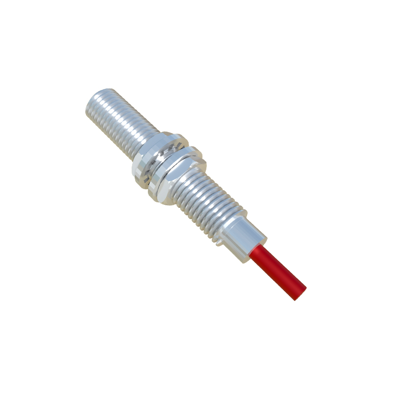
In the realm of industrial automation and electrical engineering, proximity sensors are indispensable components for detecting the presence or absence of objects without physical contact. Their symbols in electrical schematics serve as a universal language, enabling engineers and technicians to design, interpret, and troubleshoot complex systems efficiently. This article delves into the standardized symbols for various types of proximity sensors, their functional distinctions, and practical applications in circuit diagrams.
Proximity sensors are broadly categorized based on their detection principles, each represented by distinct schematic symbols. The most common types include inductive, capacitive, and photoelectric sensors. Inductive proximity sensors, designed to detect metallic objects, are typically denoted by a coil symbol enclosed in a diamond-shaped outline, often accompanied by a waveform icon to indicate electromagnetic operation. Capacitive sensors, capable of sensing both metallic and non-metallic materials, feature a similar diamond shape but include parallel plate lines inside, symbolizing the capacitive coupling effect. Photoelectric sensors, which use light beams for detection, are illustrated with a diode-like symbol emitting rays toward a receiver, encapsulated within a rectangular or diamond border depending on the variant (e.g., through-beam or retro-reflective).
These symbols are standardized by organizations such as the International Electrotechnical Commission (IEC) and the Institute of Electrical and Electronics Engineers (IEEE), ensuring consistency across global engineering documentation. In schematics, the symbol is usually integrated with additional markings to denote key specifications: output type (e.g., NPN or PNP for DC sensors, NO/NC contacts), power supply requirements, and sensing range indicators. For instance, a proximity sensor symbol might include arrows pointing inward to represent the detection direction, or labels like "SHIELDED" for sensors with embedded metal guards to reduce electromagnetic interference. Understanding these nuances is critical for accurate system integration, as misinterpreting a symbol could lead to wiring errors, operational failures, or safety hazards.
Beyond basic symbols, advanced proximity sensors—such as ultrasonic or magnetic types—have their own unique representations. Ultrasonic sensors, which measure distance using sound waves, often display a transducer icon with concentric arcs, while magnetic sensors (e.g., reed switches) use a magnet-shaped element. In complex diagrams, these symbols are linked to control units like PLCs (Programmable Logic Controllers), where they function as inputs triggering automated responses. For example, in a conveyor system, an inductive sensor symbol might connect to a relay coil, signaling the presence of a metal component to halt or divert machinery.
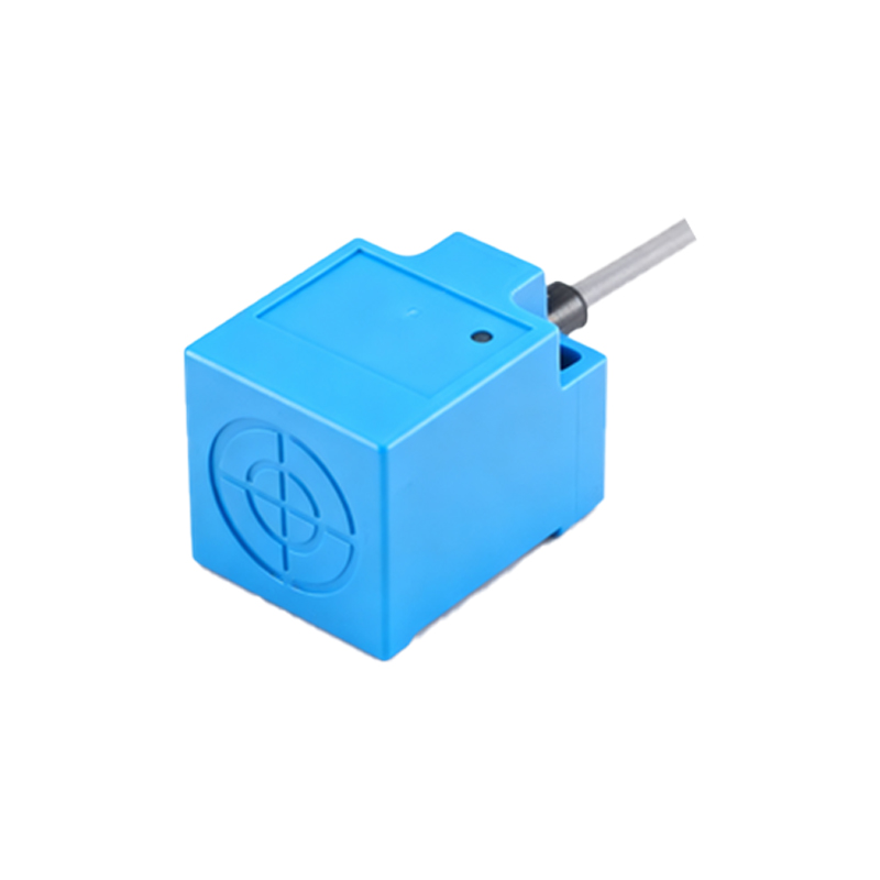
Practical application of these symbols requires familiarity with schematic conventions. Engineers must cross-reference sensor datasheets with symbol annotations to confirm parameters like voltage ratings, output configurations, and environmental tolerances. In practice, symbols are often supplemented with alphanumeric tags (e.g., "PS1" for Proximity Sensor 1) for easy identification in bill of materials (BOM) lists. As technology evolves, newer symbols have emerged for smart sensors with IO-Link or Ethernet connectivity, depicted with network nodes or communication waves adjacent to the traditional icon.
Ultimately, mastering proximity sensor symbols enhances collaboration across engineering teams and streamlines maintenance workflows. Whether designing a robotic assembly line or troubleshooting a packaging machine, clear symbol interpretation ensures systems operate reliably, minimizing downtime and optimizing productivity. By adhering to international standards and staying updated on symbol variations, professionals can navigate the intricate landscape of modern electrical schematics with confidence.