In industrial automation and machinery control, proximity sensors play a critical role in detecting the presence or absence of objects without physical contact. Their switching speed—the time it takes for the sensor to react to a target and send a signal—is a vital parameter that directly impacts system efficiency, accuracy, and reliability. Adjusting this speed correctly is not merely a technical step but a necessity for optimizing production lines, preventing malfunctions, and ensuring safety. This article provides a comprehensive guide for engineers and technicians on how to effectively adjust the switching speed of proximity sensors, covering key principles, adjustment methods, and best practices.
Understanding the fundamentals is the first step. The switching speed of a proximity sensor is typically defined by its response time, which includes both the approach time (from when the target enters the sensing range to when the output switches) and the release time (from when the target leaves the sensing range to when the output resets). This speed is influenced by several intrinsic and extrinsic factors. Intrinsic factors include the sensor's internal circuitry design, the type of output (e.g., NPN/PNP, analog, or digital), and the sensing technology (inductive, capacitive, or photoelectric). For instance, high-speed inductive sensors can achieve response times below 0.1 ms, while standard models might range from 1 to 10 ms. Extrinsic factors encompass the target material, size, and approach angle, environmental conditions like temperature and electrical noise, and the characteristics of the connected load (e.g., PLC input modules, relays).
The primary method for adjusting switching speed involves configuring the sensor itself and its connected system. Most modern programmable proximity sensors offer adjustable parameters via built-in potentiometers, DIP switches, or software interfaces. Here is a step-by-step approach:
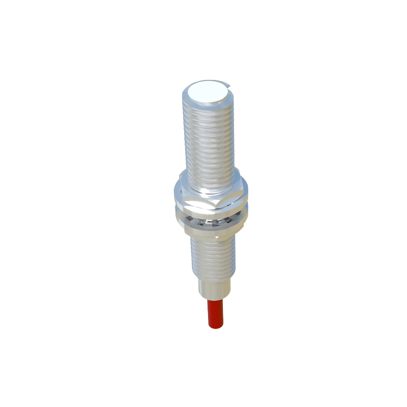
1. Consult the Datasheet: Always begin by reviewing the manufacturer's datasheet for the specific sensor model. It provides the allowable adjustment range for response time, wiring diagrams, and crucial warnings.
2. Identify Adjustment Points: Locate the adjustment mechanism. For sensors with a potentiometer, it is often a small screw labeled "Response," "Delay," or "Speed." For digital sensors, parameters might be accessible via a teach-in button or communication protocol (e.g., IO-Link).
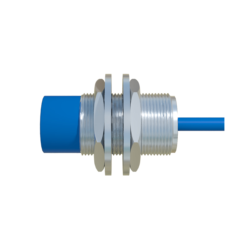
3. Initial Setup and Safety: Ensure the system is in a safe state, preferably powered down during initial wiring. Verify the power supply voltage is within specifications and the load is correctly connected.
4. Adjusting Response Time: Using a non-metallic tool, turn the potentiometer gradually. Typically, rotating clockwise increases the response time (introduces a delay), making the sensor slower but more immune to electrical noise or vibration. Rotating counterclockwise decreases the response time, making it faster. The goal is to find the fastest stable setting without false triggering.
5. Testing and Validation: After adjustment, conduct rigorous testing. Use a representative target and move it at the operational speed. Monitor the sensor's output with an oscilloscope or a PLC to observe the actual response time and signal stability. Check for missed detections or false signals under all expected operating conditions.
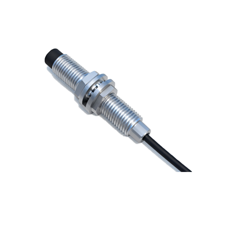
6. Hysteresis Consideration: Be aware of sensor hysteresis—the difference between the switch-on and switch-off points. Adjusting speed may indirectly affect hysteresis. A very fast setting with minimal hysteresis might cause chattering if the target oscillates near the sensing edge.
For systems requiring more sophisticated control, external timers or delay relays can be added to the sensor's output circuit. This allows introducing precise ON-delays or OFF-delays, effectively controlling the speed of the output signal relative to the detection event. This method is useful when the sensor's internal adjustment range is insufficient.
Environmental optimization is equally important. Electrical noise from motors, variable frequency drives (VFDs), or welding equipment can induce false switching. To achieve higher reliable speeds:
Use shielded cables and proper grounding.
Install filters or ferrite cores on signal lines.
Increase the separation distance between sensor cables and power lines.
Select sensors with high noise immunity ratings (e.g., IEC 60947-5-2).
Furthermore, the target itself must be suitable. For inductive sensors, a standard ferrous target should be at least the size of the sensor's active face. For non-ferrous metals, the sensing distance reduces, potentially affecting reliable high-speed detection. Ensure the target approaches the sensor perpendicularly for the most consistent response.
In high-speed applications like packaging, sorting, or assembly robots, even a millisecond matters. Here, selecting the right sensor from the outset is paramount. Consider "Factor 1" sensors designed for ultra-high-speed applications, or specialized models with push-pull outputs for faster switching into capacitive loads.
Finally, documentation and maintenance are key