In the realm of industrial automation and precision sensing, proximity sensors are indispensable components. Among their internal structures, the ferrite core shim plays a critical, though often overlooked, role. This article delves into the technical specifics of proximity sensor ferrite core shims, supported by detailed image analysis to aid engineers in selection, troubleshooting, and design optimization.
The primary function of a ferrite core shim in an inductive proximity sensor is to fine-tune the sensor's magnetic field characteristics. Typically constructed from a soft ferrite material—such as manganese-zinc (MnZn) or nickel-zinc (NiZn)—the shim is a thin, precisely manufactured spacer or washer. Its placement, usually between the ferrite core and the sensor coil or housing, directly influences the sensor's sensitivity, sensing range, and temperature stability. High-quality images reveal the shim's geometry: common shapes include flat washers, E-cores, or pot cores with specific cutouts. The surface finish, visible under magnification, should be smooth and free from micro-cracks to prevent magnetic flux leakage and performance degradation.
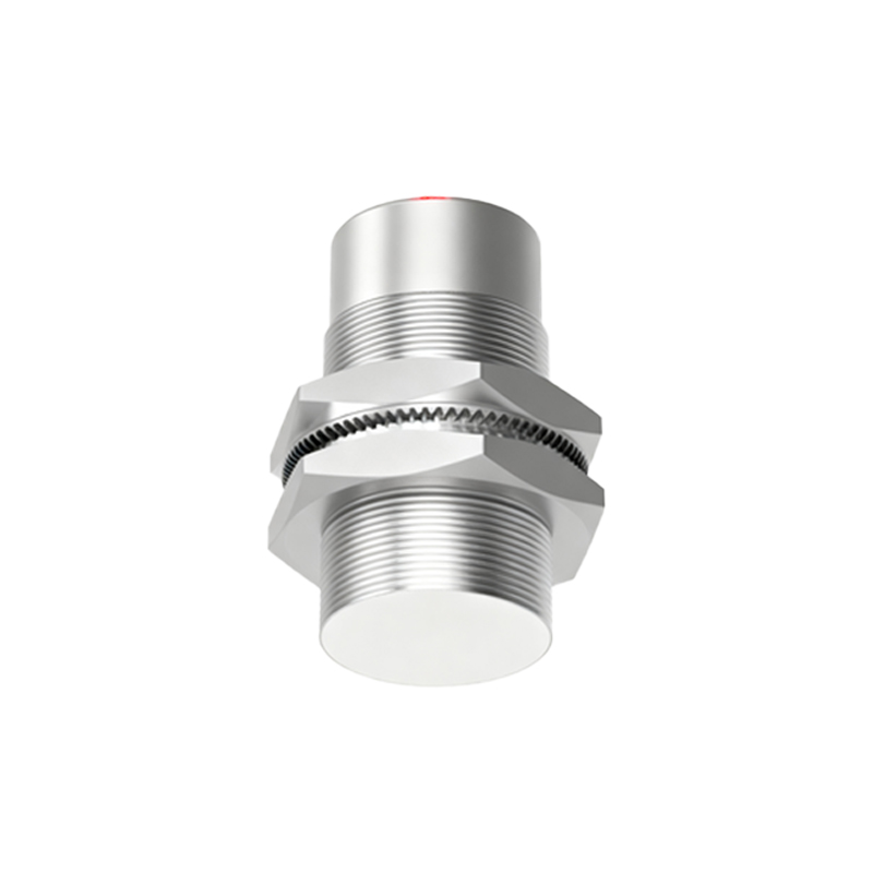
From an imaging perspective, several key details are paramount. Macro photographs showcase the shim's integration within the sensor assembly, highlighting its position relative to the oscillator coil and the sensing face. Cross-sectional diagrams or cutaway view images are invaluable, illustrating how the shim affects the path and concentration of the magnetic field lines. Microscopic images, often at 50x to 200x magnification, are crucial for quality inspection. They allow engineers to examine the material's grain structure, check for uniformity, and identify defects like porosity or uneven sintering that could compromise magnetic permeability (µ) and initial permeability (µi). Thermal imaging, while less common, can demonstrate the shim's performance under operational thermal loads, ensuring its Curie temperature is not exceeded, which would cause a sudden loss of magnetic properties.
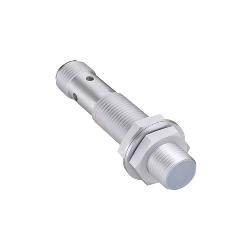
Selecting the correct shim involves analyzing these images against datasheet parameters. Key specifications include thickness (often between 0.1mm to 1.0mm), inner/outer diameter, magnetic permeability, and frequency response. For instance, a thicker, high-permeability MnZn shim might be used in low-frequency, high-sensitivity applications to extend the sensing range. In contrast, a thinner NiZn shim might be selected for high-frequency applications due to its higher resistivity and reduced eddy current losses. Comparative image galleries showing shims from different manufacturers can reveal subtle differences in tolerances and edge chamfering that impact fit and performance.
Common failure modes are often detectable through visual analysis. Image libraries for failure analysis might show:
- Cracking or chipping: Visible as hairline fractures in close-up images, often caused by mechanical stress during assembly or thermal cycling.
- Corrosion or oxidation: A dull, discolored surface in images compared to a new shim's smooth, dark gray finish, indicating potential moisture ingress and magnetic property loss.
- Improper seating: Assembly photos showing misalignment or gaps, leading to inconsistent sensing distances and false triggering.
For design engineers, reference images of shim prototypes are essential during the R&D phase. 3D renderings and CAD model cross-sections help in simulating magnetic fields using Finite Element Analysis (FEA) software before physical prototyping. Furthermore, high-resolution images of shims used in different sensor housings (e.g., cylindrical M8/M12, rectangular) provide practical insights into space constraints and assembly techniques.
In conclusion, a thorough understanding of proximity sensor ferrite core shims, reinforced by detailed technical imagery, is vital for ensuring sensor reliability and performance. Engineers are encouraged to build and consult comprehensive image libraries that correlate visual characteristics with empirical performance data. This practice not only streamlines troubleshooting and maintenance but also informs the development of next-generation sensors with enhanced precision and durability. Always refer to the specific manufacturer's technical documentation and image references for the most accurate application guidance.