Proximity sensors are essential components in modern industrial automation, providing non-contact detection of metallic or non-metallic objects. Proper wiring is critical to ensure reliable operation, safety, and longevity of these sensors. This guide outlines standard wiring practices for common types of proximity sensors, including inductive, capacitive, and ultrasonic variants, in alignment with international electrical standards such as IEC 60947-5-2.
Most industrial proximity sensors feature three or four wires, typically color-coded for easy identification. For a standard 3-wire DC sensor, the wiring configuration is as follows: the brown wire connects to the positive supply voltage (typically +24V DC), the blue wire to the negative or common ground, and the black wire is the output signal line. In sourcing (PNP) sensors, the black wire supplies positive voltage to the load when an object is detected. In sinking (NPN) sensors, the black wire connects the load to ground upon detection. It is crucial to verify the sensor’s specification sheet to determine whether it is PNP or NPN, as incorrect wiring can lead to malfunction or damage.
For 4-wire sensors, an additional wire (often white) provides a complementary output, allowing both normally open (NO) and normally closed (NC) operation. This configuration enables flexible integration into control systems, such as PLCs (Programmable Logic Controllers) or relay modules. When connecting to a PLC, the sensor’s output wire is linked to the input module, while the power supply is shared across the system. Ensure the sensor’s voltage rating matches the power source—common ratings include 10-30V DC or 90-250V AC. Overvoltage or reverse polarity can permanently damage the sensor.
Shielding and grounding are vital in electrically noisy environments. Use shielded cables, with the shield grounded at one end only (preferably at the control panel), to prevent electromagnetic interference (EMI) from causing false triggers. Maintain proper cable routing, keeping sensor wires away from high-voltage lines, motor drives, and frequency inverters. For long cable runs, consider using twisted-pair cables to reduce noise pickup and voltage drop.
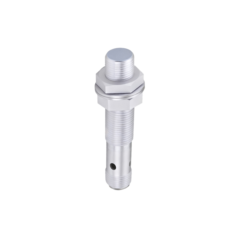
In hazardous locations, such as areas with explosive atmospheres, select intrinsically safe or explosion-proof sensors certified for the specific zone (e.g., ATEX, IECEx). Wiring must adhere to strict conduit and sealing requirements to prevent ignition risks. Always de-energize the circuit before wiring, and use appropriate tools, such as insulated crimp connectors or terminal blocks, to secure connections. Regularly inspect wires for abrasion, corrosion, or loose terminals, as these can lead to intermittent failures.
For capacitive proximity sensors, which detect non-metallic materials, ensure the sensing face is free from contamination and maintain adequate clearance from surrounding objects to avoid parasitic capacitance effects. Ultrasonic sensors require careful alignment and stable mounting to prevent false echoes. Follow the manufacturer’s guidelines for sensing distance and environmental conditions, as temperature fluctuations or humidity can impact performance.
In summary, correct proximity sensor wiring involves matching the sensor type to the application, adhering to color codes and polarity, implementing noise reduction measures, and complying with safety standards. By following these practices, engineers can optimize system reliability, reduce downtime, and enhance operational efficiency in industrial settings.