In the realm of industrial automation and control systems, proximity sensors are indispensable components for detecting the presence or absence of an object without physical contact. Among the various types, 3-wire DC sensors, specifically those with PNP and NPN output configurations, are the most prevalent. A clear understanding of the distinction between PNP and NPN proximity sensors is crucial for proper system design, wiring, and troubleshooting. This guide delves into the operational principles, wiring schematics, and practical application scenarios for both types, empowering engineers to make informed selections.
At their core, both PNP and NPN sensors function on the same basic principle: they generate an electromagnetic field and detect changes caused by a metallic or sometimes non-metallic target. The key difference lies not in the sensing element itself, but in the type of transistor used in their output switching circuit and the resulting current flow. This difference fundamentally dictates how the sensor integrates with a Programmable Logic Controller (PLC) or other control device.
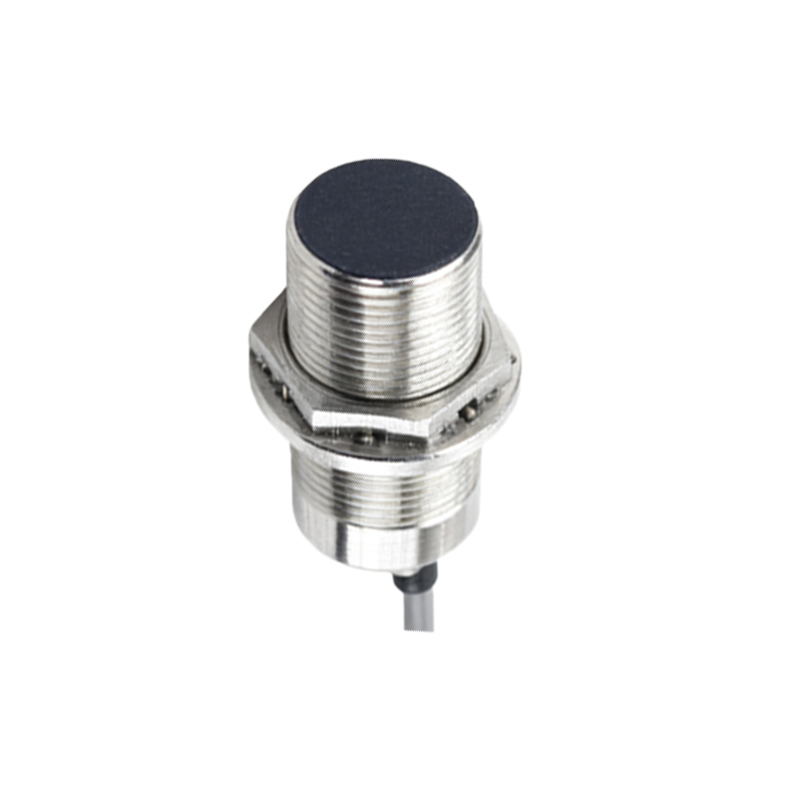
A PNP sensor, utilizing a PNP transistor, is often described as "sourcing" output. In its normal state (no target detected), the output signal wire is disconnected from the positive supply voltage. When a target is detected, the internal PNP transistor switches ON, connecting the output signal wire to the positive supply voltage (typically +24V DC). This action "sources" current from the sensor's output terminal to the load (e.g., the PLC input module). The load is then connected between the sensor's output signal wire and the common negative (0V) line. In simpler terms, the PNP sensor provides the positive voltage to the PLC input when activated.
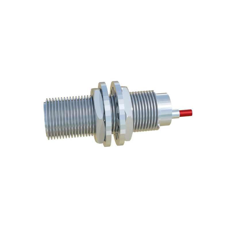
Conversely, an NPN sensor, built with an NPN transistor, is termed a "sinking" output. In its normal state, the output signal wire is disconnected from the common negative (0V). Upon target detection, the internal NPN transistor switches ON, connecting the output signal wire to the common negative (0V). This action "sinks" current from the load into the sensor. Here, the load (the PLC input) is connected between the positive supply voltage and the sensor's output signal wire. Thus, the NPN sensor provides a path to ground (0V) for the PLC input when activated.
The wiring diagrams illustrate this critical distinction. For a PNP sensor, the brown wire is typically connected to +V (e.g., +24VDC), the blue wire to 0V (common), and the black wire is the switched positive output. For an NPN sensor, the brown wire remains +V, the blue wire 0V, but the black wire becomes the switched negative (0V) output. Incorrectly matching a sensor type to a PLC input can result in a non-functional system or potential damage.
The choice between PNP and NPN is largely determined by the input circuit architecture of the controller. Many modern PLCs offer configurable input cards that can accept either type. However, traditional conventions often see PNP sensors as the standard in European and many international designs, where the PLC input module is typically wired to sink current. NPN sensors are historically more common in Asian and some North American applications, where PLC inputs are often wired to source current. It is absolutely essential to consult the controller's manual. A practical rule of thumb: a PNP sensor works with a sinking PLC input, and an NPN sensor works with a sourcing PLC input.
Beyond regional preferences, the selection can have implications for safety and circuit design. In certain fail-safe logic designs, one type might be preferred to achieve a "high" signal versus a "low" signal in a fault condition. For instance, if a wire breaks, an NPN sensor's output might float, potentially being read as a "high" by some inputs, whereas a PNP would default to "low." Understanding the desired logic state in a failure scenario is part of robust design.
In summary, PNP and NPN proximity sensors are electrically opposite in their output switching action. PNP sources positive current to the load, while NPN sinks current from the load to ground. There is no inherent performance advantage of one over the other; the choice is purely an electrical compatibility issue with the control system. Always verify the specifications of both the sensor and the controller. By mastering this fundamental concept, engineers ensure reliable sensor integration, streamline installation, and minimize downtime in automated systems.