In industrial automation and control systems, proximity sensor switches are fundamental components, providing non-contact detection of metallic or, in some cases, non-metallic objects. A common and critical troubleshooting scenario is when the sensor's indicator light fails to illuminate upon target detection. This absence of visual confirmation can signal various underlying issues, halting processes and demanding swift, accurate diagnosis. This article delves into the primary causes of this failure, structured from power supply to the sensor's internal and external environment.
The investigation must always begin with the most fundamental element: the power supply. A sensor without correct power cannot function. First, verify that the voltage supplied matches the sensor's specifications (e.g., 10-30 VDC, 20-250 VAC). Use a multimeter to measure the voltage directly at the sensor's terminals. A reading significantly below the rated minimum, or complete absence of voltage, points to a power source or wiring issue. Check for blown fuses, tripped circuit breakers, or faulty power supplies. For DC sensors, ensure correct polarity; reverse polarity can damage internal circuits and prevent operation. Also, confirm that the load (the device being switched, like a PLC input or relay) is correctly connected and within the sensor's current rating. An overload or short circuit in the load wiring can cause the sensor's output to shut down as a protective measure, extinguishing the indicator light.
Assuming power is confirmed, the next step is to examine the sensor's setup and alignment. For inductive proximity sensors (detecting metals), the sensing distance is critical. The target object must be within the sensor's nominal sensing range (Sn). Factors like target size, material (steel, aluminum, brass), and approach angle can affect the effective range. A target that is too small, made of a less-detectable material like aluminum, or approaching from an incorrect angle may not be detected, leaving the light off. For capacitive sensors, the sensitivity adjustment is paramount. An incorrectly set sensitivity pot can prevent detection of the target material or cause the sensor to be triggered by its mounting bracket or background material. Always follow the manufacturer's procedure for setting sensitivity with the actual target present.
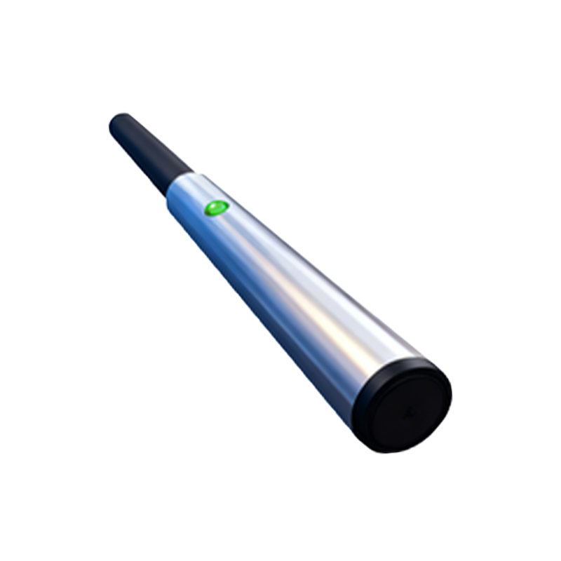
Wiring faults are a frequent culprit. Loose connections at the terminal blocks, corroded wires, or broken strands within a cable can create intermittent or complete loss of signal. Inspect the cable sheath for damage, especially near strain relief points. For 3-wire DC sensors, the standard wiring is brown (V+), blue (V- or common), and black (output). A swapped connection between the load and the common wire will prevent operation. For 2-wire AC/DC sensors, incorrect series connection with the load is a common error. The sensor must be wired in series with the load and the power supply. Vibratory environments can exacerbate wiring issues over time, leading to fatigue failure.
Environmental factors can severely degrade sensor performance. Accumulation of metallic chips, dust, oil, or coolant on the sensor's active face creates a barrier, attenuating the electromagnetic or electrostatic field. Regular cleaning of the sensing face is essential. Chemical exposure can degrade cable insulation or the sensor housing. Extreme temperatures can also cause failure; operating a sensor above or below its specified temperature range can lead to internal component drift or permanent damage. Strong electromagnetic interference (EMI) from nearby motors, welders, or frequency drives can disrupt the sensor's internal oscillator circuit, causing erratic behavior or complete shutdown. Ensure proper shielding and grounding practices are followed.
Finally, the issue may lie within the sensor itself. Internal electronic components can fail due to voltage spikes, sustained overcurrent, or simply age. A damaged oscillator circuit in an inductive sensor will prevent field generation. A failed output transistor or triac will not switch the load. If all external factors—power, wiring, setup, target, and environment—have been systematically ruled out, the sensor is likely defective. Before replacement, if possible, swap the suspect sensor with a known-good unit of the same model in the same application. If the known-good unit works, it confirms the original sensor's failure.
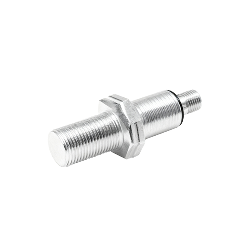
In conclusion, a methodical, step-by-step approach is key to diagnosing a proximity sensor with a non-illuminating indicator light. Start with power verification, proceed to setup and alignment, inspect all wiring thoroughly, assess environmental conditions, and finally, consider sensor failure. Documenting such troubleshooting procedures not only resolves immediate downtime but also builds a valuable knowledge base for preventing future occurrences. Always consult the specific sensor's datasheet for wiring diagrams, specifications, and diagnostic LEDs patterns, as modern sensors often include multi-status indicators for more detailed fault information.