Proximity angle sensors are fundamental components in modern industrial automation, robotics, and motion control systems. Their primary function is to detect the angular position or rotational movement of a target object without physical contact. Understanding their working principle is crucial for engineers designing precise and reliable systems. This article provides a detailed, diagram-supported explanation of how these sensors operate.
At its core, a proximity angle sensor detects the presence and angular orientation of a ferromagnetic or conductive target, typically a gear, cam, or a specially shaped rotor. The most common types are inductive and Hall-effect based sensors. We will focus on the inductive type, widely used for its robustness.
Basic Operating Principle: Inductive Sensing
An inductive proximity angle sensor consists of a coil wound around a ferrite core, an oscillator circuit, a demodulator, and a switching circuit. The coil and oscillator generate a high-frequency electromagnetic field at the sensing face. When a metallic target (like a gear tooth) approaches this active field, eddy currents are induced on the target's surface. These eddy currents draw energy from the oscillator, causing a reduction in the amplitude of oscillation. The demodulator circuit detects this amplitude change and triggers the output circuit to switch states. Conversely, when the target moves away (e.g., a gear valley), the oscillation amplitude increases, and the output switches back.

Key Component: The Target
For angular measurement, the target is rotational. A common configuration uses a ferrous gear wheel mounted on a rotating shaft. The sensor is positioned such its face is aligned radially towards the gear teeth. As the gear rotates, the alternating sequence of teeth (high points) and valleys (low points) passes by the sensor. Each tooth passage causes the sensor output to pulse. By counting these pulses and knowing the number of teeth on the gear, a control system can calculate the shaft's angular displacement and speed.
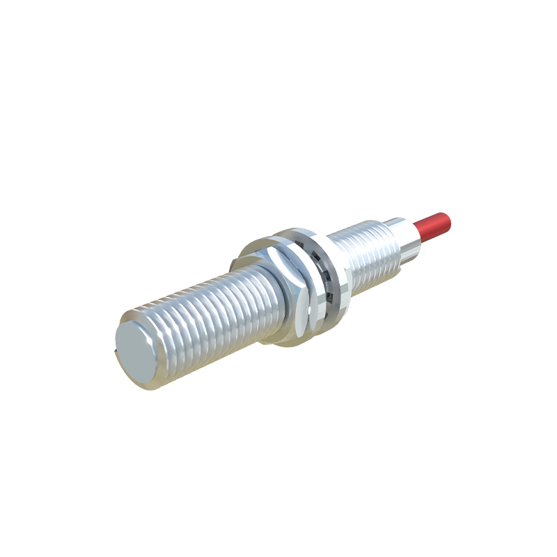
Diagrammatic Explanation
Diagram A (Static Field): Shows the sensor's electromagnetic field radiating from its face with no target present. The oscillator runs at full amplitude.
Diagram B (Tooth Approach): Illustrates a gear tooth entering the sensing field. The field lines become concentrated in the tooth. Eddy currents flow, damping the oscillation.
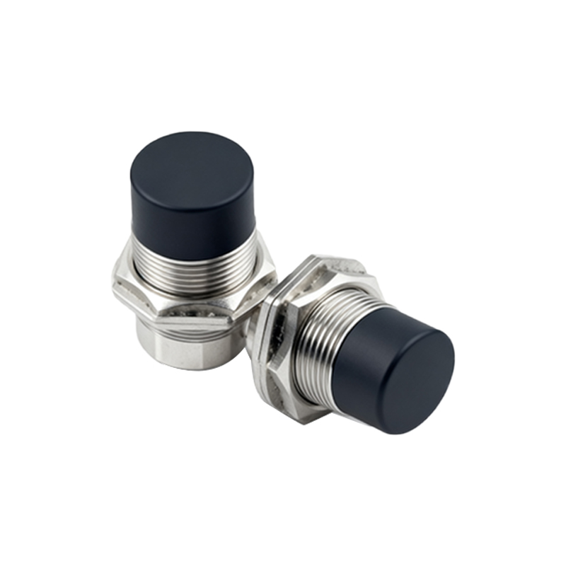
Diagram C (Tooth Aligned): Depicts the tooth directly in front of the sensor. Eddy current generation is maximum, oscillation is minimum, and the sensor's output is active (e.g., switches to ON or HIGH).
Diagram D (Valley Passage): Shows a valley (space between teeth) in front of the sensor. The field is less disturbed, oscillation amplitude recovers, and the output switches off.
This ON/OFF pulse train is the fundamental output. The angular resolution is determined by the number of teeth on the target gear. A 60-tooth gear, for instance, generates one pulse per 6 degrees of rotation (360/60=6).
Advanced Function: True Angle Position Sensing
For applications requiring absolute angular position (not just incremental pulses), a different target design is used. Instead of a standard gear, a specially coded disk (with a unique pattern of conductive/non-conductive or magnetic/non-magnetic segments) is attached to the shaft. Multiple sensor elements are arranged to read this pattern simultaneously. The combined output from these sensors creates a unique digital code (e.g., Gray code) for every discrete angular position of the shaft within one full revolution. This provides an absolute position reading upon power-up, eliminating the need for a homing sequence.
Hall-Effect Angle Sensors
Another prevalent technology uses Hall-effect elements. These sensors detect changes in magnetic field strength. A permanent magnet is mounted on the rotating shaft, and a Hall-effect IC is positioned stationary. As the magnet rotates, the angle between its magnetic field vector and the Hall plate changes, which alters the output voltage of the sensor. Integrated signal processing chips can then translate this voltage into a precise analog (0.5-4.5V) or digital (PWM, SENT) output proportional to the absolute angle from 0 to 360 degrees. These are often called rotary or angle position sensors.
Critical Performance Factors
Engineers must consider several parameters:
1. Switching Frequency: The maximum number of output pulses per second, limiting the maximum detectable speed.
2. Hysteresis: A built-in difference between the switch-on and switch-off points to prevent output chatter when the target is at the exact sensing boundary.
3. Temperature Range: Industrial sensors must operate reliably across wide temperature swings.
4. Air Gap: The permissible distance between the sensor face and the target, which affects signal strength and consistency.
5. Output Type: PNP, NPN, analog, or digital outputs to interface with PLCs,