In the realm of industrial automation and electrical control systems, proximity switch sensors are indispensable components. They detect the presence or absence of an object without physical contact, relying on electromagnetic fields, capacitance, or other principles. A critical parameter for diagnosing sensor health, especially for inductive and capacitive types, is electrical resistance. Understanding how to accurately measure the resistance of a proximity switch sensor is a fundamental skill for maintenance engineers and technicians. This guide provides a detailed, step-by-step procedure, essential precautions, and interpretation of results.
Before initiating any measurement, safety is paramount. Always ensure the sensor is completely disconnected from its power source and any associated control circuitry, such as PLCs or relays. Lock-out/Tag-out (LOTO) procedures should be strictly followed. Allow the sensor to cool if it has been operating, as temperature can affect resistance readings. Gather the necessary tools: a high-quality digital multimeter (DMM) with resistance (Ω) measurement capability, appropriate test leads, and the sensor's datasheet for reference values.
The first step is terminal identification. A standard 3-wire DC proximity sensor typically has three connections: brown wire (positive supply, +V), blue wire (negative supply, 0V or common), and black wire (signal output). For a 2-wire AC/DC sensor, there are only two wires for both power and signal. Resistance measurements are most commonly performed on the sensor's output circuit relative to the common terminal. It is crucial to note that you are measuring the resistance of the internal switching element (often a transistor) and not the coil of an inductive sensor directly.
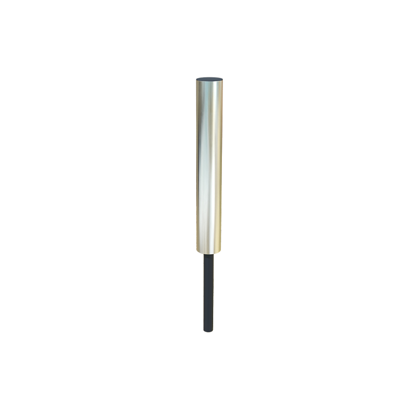
Here is the detailed measurement procedure for a common 3-wire DC NPN or PNP sensor:
1. Set your digital multimeter to the resistance mode, typically denoted by the Ω symbol. Start with a mid-range setting like 200kΩ.
2. Identify the sensor's common (blue) wire and output (black) wire. Refer to the datasheet if wire colors are non-standard or unclear.
3. For an NPN sensor (sinking output): Place the multimeter's red probe on the blue (common) terminal and the black probe on the black (output) terminal. For a PNP sensor (sourcing output): Place the black probe on the blue (common) terminal and the red probe on the black (output) terminal. This aligns the multimeter's internal battery polarity with the sensor's output transistor.
4. Observe the reading on the multimeter display.
Interpretation of the readings is key:
- Normal "Off-State" Resistance: When the sensor is not activated (no target present), a healthy switching transistor should show a very high resistance, often displayed as "OL" (Over Limit) or several megaohms (MΩ). This indicates the switch is "open."
- Normal "On-State" Resistance: Activate the sensor by presenting a valid target at its specified sensing distance. The resistance should drop to a relatively low value, typically between a few ohms to a few hundred ohms, depending on the sensor's design and current rating. This indicates the switch is "closed."
- Faulty Readings:
- Consistently Very High Resistance (OL): If the reading remains OL even when the sensor is activated, the output transistor may be open-circuited or damaged.
- Consistently Very Low Resistance (near 0Ω): If the reading is very low even without a target, the output transistor may be short-circuited.
- Erratic or Unstable Readings: This can indicate internal damage, moisture ingress, or a failing component.
For 2-wire sensors, the procedure is similar but simpler. Measure the resistance across the two wires. You should observe a high resistance in the off-state and a lower resistance in the on-state. The actual values will be higher than for 3-wire sensors because the measured path includes the entire sensor's operating circuit.
Important considerations include the use of the diode test function. Some multimeters have a diode test mode (⎓⏚). This can be useful for checking the health of the output transistor, as it will show the forward voltage drop (typically 0.4-0.7V for a healthy silicon transistor) when the probes are connected in the correct polarity with the sensor activated. Always compare your measured values with the specifications in the manufacturer's datasheet. Ambient temperature can affect readings; a sensor might measure differently when hot versus cold. Resistance checks are a vital part of troubleshooting, but they should be combined with functional tests under powered conditions (using a load resistor or PLC input) and voltage measurements to confirm overall sensor operation.
In conclusion, measuring the resistance of a