Point laser sensors are indispensable tools in modern industrial automation, offering high precision for detection, measurement, and positioning tasks. Proper wiring is fundamental to their reliable operation, safety, and integration into a control system. This guide provides a detailed, step-by-step approach to wiring a typical point laser sensor, covering essential principles, safety protocols, and common configurations.
Before handling any electrical components, ensure all power sources to the control panel or machine are locked out and tagged out (LOTO). Verify the sensor’s datasheet, as specifications for voltage, current, output type, and pin assignments vary significantly between models (e.g., PNP vs. NPN, analog vs. digital). Gather necessary tools: appropriate wire gauges (often 0.25-0.75 mm²), ferrules, a wire stripper, a screwdriver, and the sensor’s connector or terminal housing.
A standard point laser sensor typically has four to six connection points, though simpler models may have three. The core connections are:

1. Power Supply (V+ and V- or 0V): This provides operating voltage. Most industrial sensors use 10-30V DC. Connect the positive lead (often brown or red wire) to the DC positive supply (e.g., +24V). Connect the negative or 0V lead (often blue or black wire) to the DC common or ground. An unstable power supply is a common source of erratic sensor behavior.
2. Output Signal (OUT): This is the sensor’s switching or measurement signal. For a digital (on/off) sensor, this wire (often black, white, or gray) carries the signal to a PLC input module or relay. For a PNP (sourcing) sensor, the output provides positive voltage when active. For an NPN (sinking) sensor, it provides a path to ground when active. Mismatching PNP and NPN with your controller is a frequent wiring error.

3. Function Wires: Some sensors have additional wires for functions like a teach-in input (for setting thresholds), an analog output (e.g., 0-10V for distance), or a diagnostic output. These are often colored yellow or green. Consult the manual for their specific use.
Wiring Procedure:
Step 1: Prepare the Cables. Cut the cable to the required length, strip the insulation (typically 7-9mm), and crimp ferrules onto the strands. This prevents fraying and ensures a secure connection in terminal blocks.
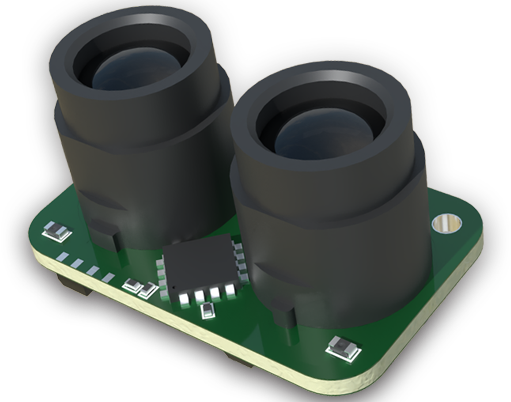
Step 2: Identify the Connector. If using a pre-molded connector, match the pin numbers or letters to the wiring diagram. For sensors with a terminal block housing, open the housing to access the screw terminals.
Step 3: Make the Connections.
* Connect the V+ wire to the designated power terminal.
* Connect the V- wire to the designated ground/common terminal.
* Connect the output signal wire to its terminal.
* Connect any function wires as needed.
Tighten all terminals firmly to avoid loose connections, which cause heat and failure, but avoid over-tightening. Ensure no stray wire strands are protruding.
Step 4: Cable Management and Shielding. Secure the cable with cable ties, avoiding sharp bends. If operating in electrically noisy environments (near motors, VFDs), use shielded cable. Connect the cable shield to a functional earth ground at the control panel end only, not at both ends, to prevent ground loops.
Step 5: Power and Test. Before restoring main power, double-check all connections against the diagram. Apply power. The sensor usually has a power-on LED. Use the manufacturer’s recommended method (e.g., a test target) to trigger the sensor and verify the output LED illuminates and the signal is correctly received by the PLC or meter.
Common Wiring Configurations:
* 2-Wire DC Sensor: These are wired in series with the load. Polarity is often critical.
* 3-Wire DC Sensor (PNP/NPN): The most common type, as described above.
* 4-Wire Sensor with Dual Output: May have both a PNP (NO) and an NPN (NC) output, or separate switching and analog outputs.
* Networked Sensors: Modern sensors may use IO-Link, which requires a standard 3-wire connection plus a fourth wire for bidirectional data communication to a master module.
Troubleshooting Tips:
* No Power LED: Check supply voltage at the sensor terminals with a multimeter. Verify fuse integrity.
* Erratic Output: Check for loose connections. Look for electrical noise interference; improve shielding and grounding. Ensure the load current does not exceed the sensor’s rated capacity.
* Incorrect Switching: Confirm PNP/NPN compatibility with the input circuit. For a PLC sinking input, a PNP sensor is required.
Proper wiring is more than just making electrical contact; it ensures signal integrity, system safety, and sensor longevity. Always prioritize the manufacturer’s documentation for your specific model, as this guide outlines general principles. Investing time in correct installation prevents costly downtime and ensures your point laser sensor performs with the precision it was designed for.