Proper installation of proximity sensors is critical for ensuring reliable operation in industrial automation systems. As an experienced electrical engineer, I have compiled this comprehensive guide with detailed images to illustrate best practices for mounting, wiring, and calibrating these essential devices. Proximity sensors, including inductive, capacitive, and ultrasonic types, detect the presence or absence of objects without physical contact, making them ideal for harsh environments where durability and precision are paramount.
The first step in installation involves selecting the appropriate sensor type based on the application. Inductive sensors are suitable for detecting metallic objects, while capacitive sensors can handle non-metallic materials. Ultrasonic sensors offer greater range and are used for level detection or distance measurement. Always refer to the manufacturer’s datasheet for specifications such as sensing distance, voltage ratings, and environmental tolerances.
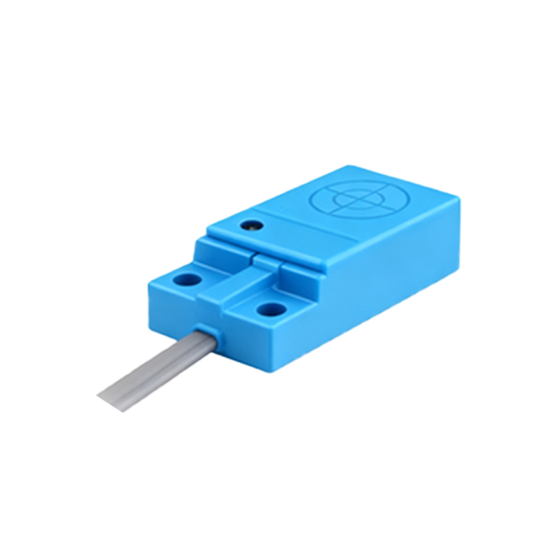
Mounting the sensor correctly is crucial to avoid false triggers or reduced sensitivity. Ensure the sensor is securely fastened using suitable brackets or housings, and maintain the recommended clearance from other objects. For example, inductive sensors require a minimum distance from metal surfaces to prevent interference. The accompanying images show examples of flush and non-flush mounting configurations, highlighting how alignment affects performance. In one image, a sensor is mounted parallel to the target object, optimizing detection accuracy, while another demonstrates incorrect angled mounting that leads to unreliable readings.
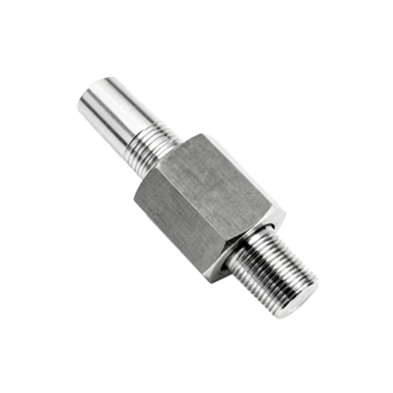
Wiring and electrical connections must adhere to safety standards. Most proximity sensors have three-wire configurations (brown for positive, blue for negative, and black for output). Use shielded cables in electrically noisy environments to prevent signal disruption. The images depict proper terminal connections, including grounding techniques and protection against short circuits. For instance, a close-up photo illustrates how to connect wires to a sensor’s M12 connector, emphasizing color-coding and strain relief to prevent disconnection.
Calibration and testing are final steps to verify functionality. Adjust the sensor’s sensitivity or hysteresis settings as needed, and use diagnostic tools like multimeters to check output signals. Images in this section show a technician testing a sensor with a metal target, confirming the LED indicator activates upon detection. Regular maintenance, such as cleaning the sensor face to remove dust or debris, is also demonstrated visually to prolong lifespan.
Common installation errors include incorrect mounting orientation, inadequate sealing in wet conditions, and ignoring temperature limits. The guide includes comparative images of correct vs. incorrect setups, such as a sensor exposed to moisture without an IP67 rating, leading to failure. By following these guidelines and referencing the visual examples, engineers can optimize sensor performance, reduce downtime, and enhance system efficiency in applications ranging from conveyor belts to robotic arms.