In the realm of industrial automation and machine design, proximity sensors are indispensable components for non-contact object detection. Among their critical specifications, the output current rating—commonly 200mA or 300mA—is a fundamental parameter that significantly influences sensor selection, system integration, and overall reliability. This article delves into the technical distinctions, application considerations, and practical implications of choosing between 200mA and 300mA rated proximity sensors.
At its core, the current rating of a proximity sensor, indicated in milliamperes (mA), defines the maximum continuous load current its solid-state output switch can safely handle. This specification is paramount for the sensor's output stage, typically a PNP (sourcing) or NPN (sinking) transistor. A 200mA sensor is designed to switch loads drawing up to 200 milliamperes, while a 300mA sensor offers a higher capacity of 300 milliamperes. This difference directly correlates to the electrical load the sensor can control without risk of overheating or failure.
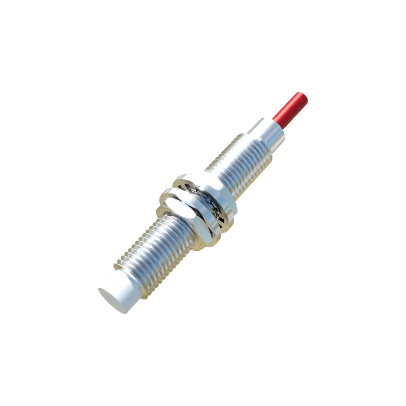
The choice between these ratings is not arbitrary but is dictated by the electrical characteristics of the load being controlled. Common loads include relay coils, solenoid valves, PLC (Programmable Logic Controller) input modules, and indicator lamps. A 200mA output is often sufficient for driving many standard PLC digital inputs, which typically have low current requirements, or small pilot relays. It represents a robust and common standard in many automation systems, offering a good balance between capability and cost. Sensors with this rating are widely available and suitable for a vast array of standard applications where load currents are well within this limit.
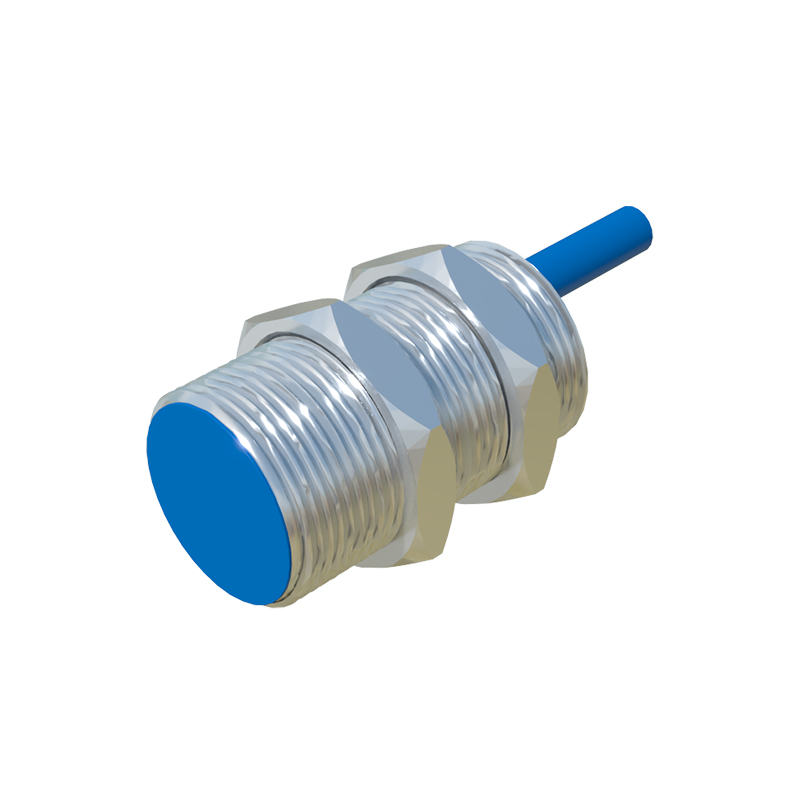
In contrast, a 300mA output rating provides a substantial margin of safety and additional drive capability. This becomes crucial when directly interfacing with devices that have higher inrush or holding currents. For instance, certain larger solenoid valves, contactor coils, or small motors might demand currents closer to the 200mA threshold. Using a 300mA sensor in such scenarios ensures the sensor operates well within its specifications, reducing thermal stress and enhancing long-term reliability. It effectively future-proofs the design, allowing for load changes without necessitating sensor replacement. Furthermore, in safety-critical or high-availability systems, the derating principle—using a component well below its maximum rating—often makes the 300mA sensor the preferred choice even for loads under 200mA, as it promotes enhanced durability and operational stability.
From a design perspective, engineers must carefully calculate the total load current. This includes considering the steady-state current and, importantly, any inrush current that occurs when the load is first energized. Inductive loads like coils can have inrush currents several times higher than their normal operating current. While many proximity sensors are designed to withstand short-term overloads, consistently operating near or at the maximum 200mA limit with such peaks can shorten the sensor's lifespan. Therefore, selecting a 300mA sensor provides a necessary buffer, ensuring the inrush current remains a smaller percentage of the sensor's maximum capacity.
Physical construction and heat dissipation are also tied to the current rating. A 300mA output transistor typically requires a more robust design to manage the higher potential power dissipation (heat). This can influence the sensor's housing size and material. While often similar in external dimensions, a 300mA-rated sensor may have slightly different internal thermal management. It is essential to consult manufacturer datasheets for detailed specifications on continuous current, switching frequency, and ambient temperature limits, as these factors interrelate. A high switching frequency can reduce the effective continuous current a sensor can handle due to heat buildup.
In practical application scenarios, the decision matrix is clear. For standard machine automation, controlling PLC inputs, or switching small relays, a 200mA proximity sensor is typically cost-effective and perfectly adequate. Its widespread use has made it a de facto standard for many OEMs. However, for heavy-duty cycles, harsh environments with elevated temperatures, direct control of power-hungry devices, or in applications where maintenance access is difficult and reliability is paramount, the investment in a 300mA sensor is justified. The marginally higher unit cost is often offset by reduced downtime and longer mean time between failures (MTBF).
In conclusion, the selection between a 200mA and a 300mA proximity sensor is a critical engineering decision rooted in load analysis and system design philosophy. The 200mA sensor serves as the reliable workhorse for countless standard applications. Meanwhile, the 300mA sensor offers superior robustness, a safety margin for demanding loads, and contributes to a more resilient automation system. By thoroughly evaluating the load requirements, including inrush currents and operational duty cycles, engineers can specify the optimal sensor, ensuring both performance efficiency and long-term operational integrity on the factory floor.