Inductive proximity sensors are fundamental components in modern industrial automation, serving as the eyes of countless machines by detecting the presence or absence of metallic objects without physical contact. A critical, yet sometimes overlooked, aspect of these sensors is their indicator light system. This guide delves into the functionality, interpretation, and troubleshooting of these LED indicators, providing essential knowledge for engineers and technicians.
The primary purpose of the indicator light, typically a Light Emitting Diode (LED), is to provide real-time visual feedback on the sensor's operational status. This simple feature is a powerful diagnostic tool. In most standard three-wire DC sensors (PNP or NPN), the LED illuminates when the sensor detects a target within its sensing range. This "switching state" indication confirms that the sensor is active and has successfully triggered its output signal. Conversely, when no target is present, the LED remains off, signifying the output is in its normal, non-active state.
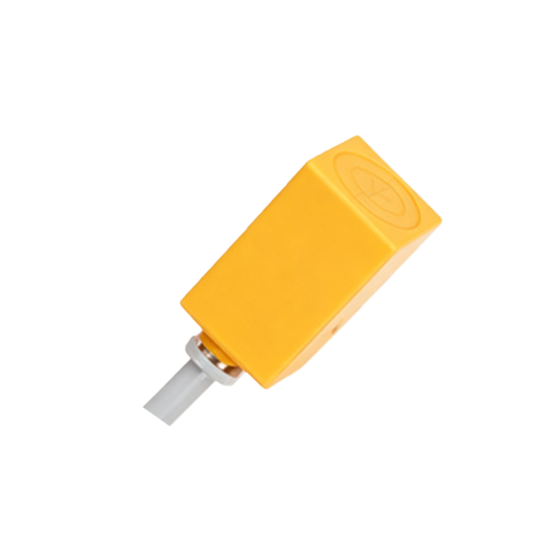
However, the indicator's role extends beyond mere target detection. Modern inductive proximity sensors often use the LED to communicate power status, error conditions, and operational health. A steadily illuminated LED when no target is present could indicate a short-circuit condition or that the sensor is in a "teach" or configuration mode. A rapidly blinking LED might signal an overload condition, wiring fault, or that the sensing distance is improperly calibrated. It is paramount to consult the specific sensor's datasheet, as blinking patterns and colors (if multi-color LEDs are used) are manufacturer-specific codes. For instance, two short blinks followed by a pause could indicate a voltage supply issue, while a continuous, slow blink might denote a temperature warning.
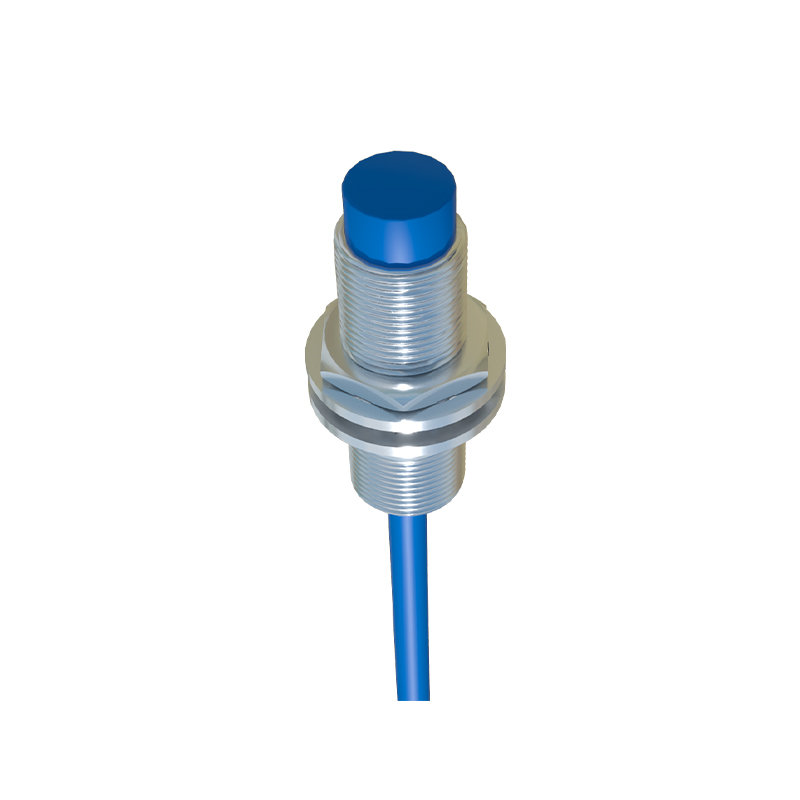
Understanding the electrical configuration is key to correct interpretation. For a 3-wire DC PNP sensor (sourcing), the brown wire is typically connected to positive DC voltage (+V), the blue wire to common negative (0V), and the black wire is the switched positive output. The internal LED is usually wired in parallel with the output switching element. When the sensor detects a target, it closes the circuit between the black and brown wires, allowing current to flow to the load and simultaneously illuminating the LED. In NPN (sinking) sensors, the logic is inverted; the black wire provides a switched path to 0V. The LED behavior regarding target detection remains visually the same—on for detection, off for no detection—but the underlying circuit differs.
Two-wire AC/DC sensors also feature indicator lights, but their operation is integrated into the main current path. The LED illuminates when the sensor is conducting current in its "on" state to power the connected load. The brightness might vary slightly with the load current. A dim or flickering LED on a two-wire sensor can point to insufficient load current (below the minimum operating current) or a leaky load.
From a maintenance perspective, the indicator light is the first line of defense in troubleshooting. A sensor that fails to trigger a machine cycle can be quickly assessed. If the LED illuminates when a target is presented, the issue likely lies downstream—in the PLC input module, wiring, or the program logic. If the LED fails to illuminate, the problem is with the sensor itself or its immediate power supply. Checks should include verifying supply voltage polarity and magnitude, ensuring the target is of the correct material (ferrous or non-ferrous metal) and size, and confirming the target is within the rated sensing distance. Environmental factors like excessive metal chips, extreme temperatures, or strong electromagnetic interference can also cause erratic LED behavior or sensor failure.
Furthermore, advanced sensors with IO-Link or AS-Interface connectivity use LED patterns to indicate communication status, device identification, and parameterization modes. A solid green light might mean normal operation and communication, while an alternating red/green flash could indicate active parameter download.
In conclusion, the humble indicator light on an inductive proximity sensor is a vital communication interface. It transforms the sensor from a simple switch into an intelligent device capable of announcing its state and health. Mastering its language—by cross-referencing observed behavior with technical documentation—empowers engineers to ensure system reliability, minimize downtime, and perform efficient, targeted maintenance. Always prioritize the manufacturer's manual for the definitive key to your specific sensor's luminous signals.