Proximity sensors are widely used in industrial automation for detecting the presence or absence of objects without physical contact. Proper wiring is crucial for ensuring reliable operation and safety. This article provides an overview of common proximity sensor wiring methods, supported by illustrative diagrams, to guide engineers and technicians in correct installation.
There are several standard wiring configurations for proximity sensors, primarily based on their output type and power supply requirements. The most common types include two-wire, three-wire, and four-wire sensors, each with distinct connection approaches.
Two-wire proximity sensors are the simplest type, consisting of only two wires for both power supply and load connection. They are directly connected in series with the load and power source. While easy to install, they may have higher residual current and voltage drop limitations. A typical wiring diagram shows the sensor connected between the positive supply line and the load, with the load then linked to the negative or ground line. This configuration is often used in basic on/off applications.
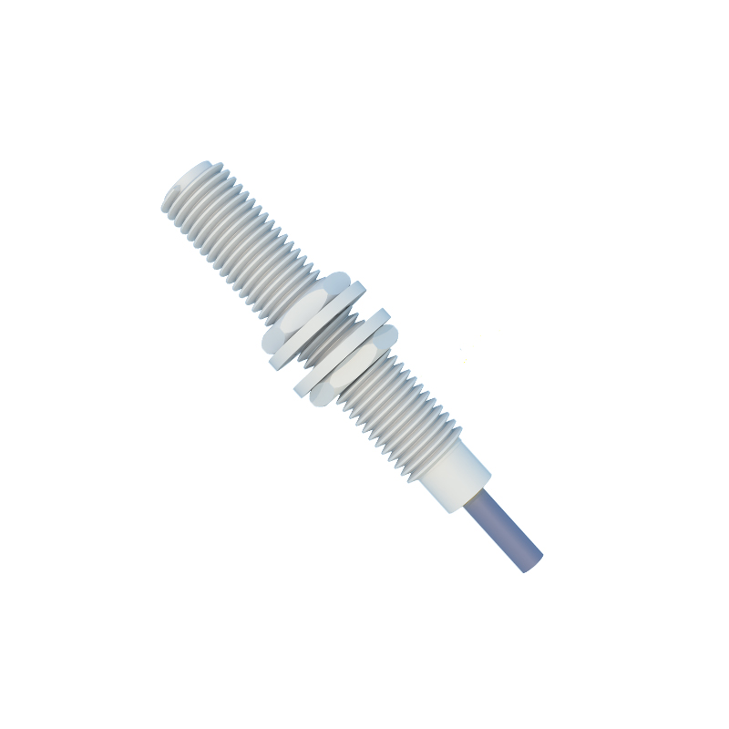
Three-wire proximity sensors are the most prevalent in industrial settings. They feature separate wires for power supply, ground, and output signal. These sensors come in two output polarities: NPN (sinking) and PNP (sourcing). In an NPN configuration, the output switches the negative side of the load to ground, while in a PNP setup, the output switches the positive side to the load. Wiring diagrams for three-wire sensors clearly indicate the brown wire (typically +V), blue wire (0V or ground), and black wire (output signal). Proper connection to PLCs or controllers requires matching the sensor's output type with the input module's compatibility.
Four-wire proximity sensors include two output wires, allowing for both normally open (NO) and normally closed (NC) contacts. This provides flexibility in control logic. The wiring involves connecting power and ground as in three-wire sensors, with the additional output wire offering an alternative switching state. Diagrams for four-wire sensors show dual outputs, enabling selection based on application needs, such as fail-safe requirements.
Shielded cables are recommended for wiring in environments with electromagnetic interference (EMI). The shield should be grounded at one end to prevent noise from affecting sensor performance. Diagrams often depict proper grounding techniques to minimize false triggering.
When wiring proximity sensors, always refer to the manufacturer's datasheet for specific pinouts and voltage ratings. Incorrect connections can lead to sensor damage or operational failures. Use appropriate wire gauges and secure terminals to ensure stable connections. For hazardous areas, follow intrinsic safety guidelines and use certified components.
In summary, understanding proximity sensor wiring methods through diagrams enhances installation accuracy and system reliability. Whether using two-wire, three-wire, or four-wire sensors, adhering to standard practices ensures optimal performance in automation systems.