In industrial automation and control systems, proximity switch sensors are indispensable components for non-contact detection of objects. Understanding how to properly wire these sensors, particularly in a series circuit configuration, is crucial for ensuring reliable operation, safety, and system efficiency. This article delves into the technical details of a proximity switch sensor series circuit diagram, explaining its principles, common wiring practices, and key considerations for implementation.
A series circuit for proximity switches involves connecting multiple sensors in a sequence where the same current flows through each device. The fundamental principle is that all sensors must be closed (or in a conducting state, depending on the type) for the circuit to be complete and activate the load, such as a relay, PLC input, or indicator lamp. This configuration is often employed in safety-critical applications or multi-condition processes where all specified conditions must be met before an action is initiated. For instance, in a machine guarding system, multiple safety proximity sensors might be wired in series so that if any one guard door is open, the entire circuit opens, immediately halting machine operation.
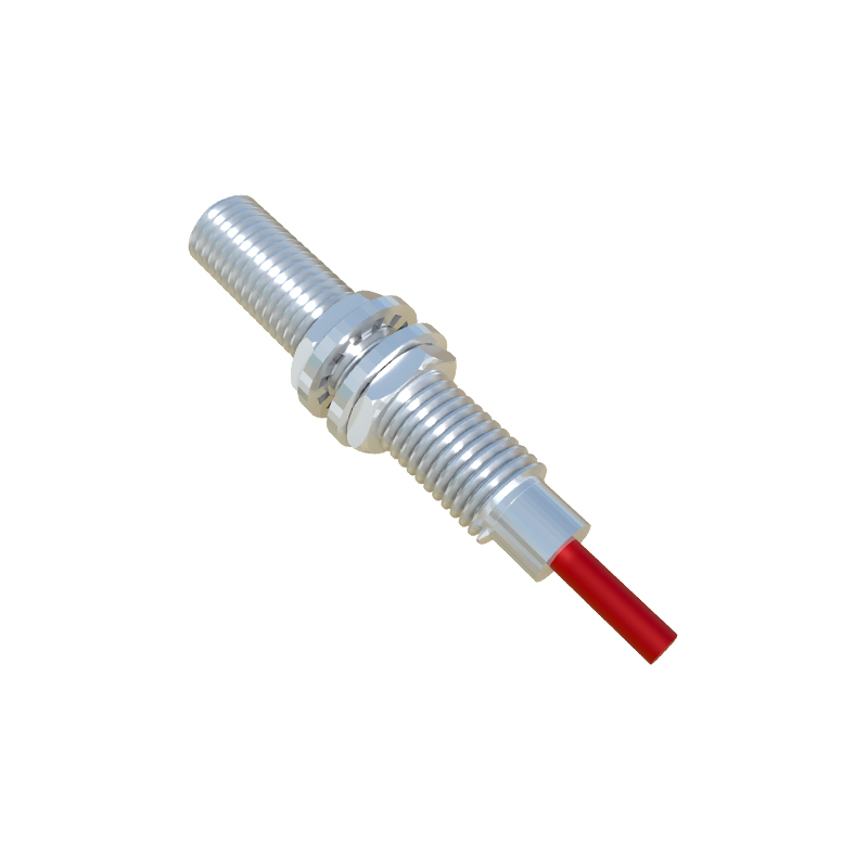
The typical circuit diagram for connecting normally open (NO) DC 3-wire proximity sensors in series is straightforward but requires attention to detail. Let's consider a setup with two inductive proximity sensors (Sensor A and Sensor B) powering a relay coil. First, the positive supply voltage (e.g., +24VDC) is connected to the brown wire (typically V+) of Sensor A. The black wire (switch output) of Sensor A is then connected not to the load directly, but to the brown (V+) wire of Sensor B. Subsequently, the black output wire of Sensor B is connected to one terminal of the relay coil. The other terminal of the relay coil connects back to the power supply common (0VDC or negative). The blue wires from both sensors are connected together to this common supply line. In this arrangement, for the relay to energize, Sensor A must detect an object (closing its internal switch) AND Sensor B must also detect an object. If either sensor does not detect a target, its output remains open, breaking the series chain and de-energizing the relay. This creates a logical AND function.
For 2-wire AC or DC proximity switches, series wiring is conceptually similar but interfaces directly with the AC line or DC supply. The live conductor (L or +) is connected to the first sensor's positive terminal, its output terminal connects to the second sensor's positive terminal, and so on, with the final sensor's output connecting to the load. The load's other side returns to the neutral (N) or negative line. It is vital to ensure that the total voltage drop across all sensors in series does not leave insufficient voltage for the load to operate correctly. Always consult the sensor datasheets for voltage drop specifications under load current.
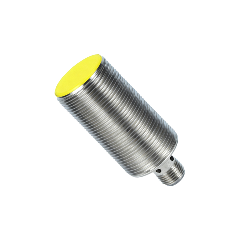
Several critical factors must be considered when designing a proximity sensor series circuit. Voltage Drop and Leakage Current: Each sensor in the series introduces a small voltage drop when conducting. With multiple sensors, this cumulative drop can be significant, potentially causing the load (e.g., a PLC digital input) to misread the signal. For 3-wire DC sensors, ensure the final voltage at the load meets its minimum "ON" state voltage requirement. Leakage current from solid-state outputs in the "OFF" state can also accumulate, possibly causing a small residual voltage that might be misinterpreted by highly sensitive inputs. Using a bleeder resistor in parallel with the load can often mitigate this. Load Compatibility: Verify that the total current drawn by the load does not exceed the current rating of any single sensor's output switch, especially the first sensor in the chain which carries the combined load current. Diagnostics and Troubleshooting: A disadvantage of a simple series circuit is diagnostic difficulty. If the load fails to activate, you must check each sensor individually to find which one is open. Incorporating diagnostic indicators at each sensor or using sensors with built-in diagnostic outputs (like a separate NO/NC auxiliary contact) can greatly simplify maintenance. Safety Considerations: For safety systems (e.g., Emergency Stop circuits), relevant standards like ISO 13849-1 or IEC 62061 often mandate monitored safety relays and specifically designed safety sensors with dual channels and cross-monitoring, rather than simple series wiring of standard sensors, to achieve required Performance Levels (PL) or Safety Integrity Levels (SIL).
In practice, while series wiring is common for basic interlock logic, modern control systems frequently handle logical AND functions programmatically within a PLC. Sensors are wired individually to separate PLC input points, and the AND logic is implemented in software. This approach offers superior diagnostics, flexibility, and often simplifies wiring. However, a hardwired series circuit remains a valid, cost-effective, and fail-safe solution for simpler applications or as a redundant backup to