In industrial automation and control systems, two-wire proximity sensors are ubiquitous components prized for their simplicity and reliability. Unlike their three-wire counterparts, these sensors integrate the switching element directly into the power loop, eliminating the need for a separate supply wire. This design makes them easier to install and wire, especially in retrofit applications or where cabinet space is at a premium. However, their wiring principles must be thoroughly understood to ensure correct operation and avoid common pitfalls. This guide provides a detailed, step-by-step explanation of how to properly wire a two-wire DC proximity sensor.
First and foremost, safety is paramount. Always ensure the power is completely locked out and tagged out (LOTO) before beginning any wiring work. Verify the sensor's specifications on its nameplate or datasheet. Critical parameters include the operating voltage range (e.g., 10-30V DC), current consumption, switching function (normally open (NO) or normally closed (NC)), and the type of target material it detects (e.g., ferrous metals for inductive sensors). Also, note the maximum load current the sensor can switch, which is typically lower than for a three-wire sensor because the sensor itself consumes a portion of the current.
The core principle of a two-wire sensor is that it acts as a variable resistance in the circuit. When the target is not present, the sensor presents a high resistance (leakage current is very low, often<1.5mA), allowing insufficient current to flow to activate the load (like a PLC input or a relay coil). When a target enters its sensing range, the sensor's internal resistance drops significantly, allowing sufficient current to flow to both power itself and activate the connected load.
Here is the standard wiring procedure:
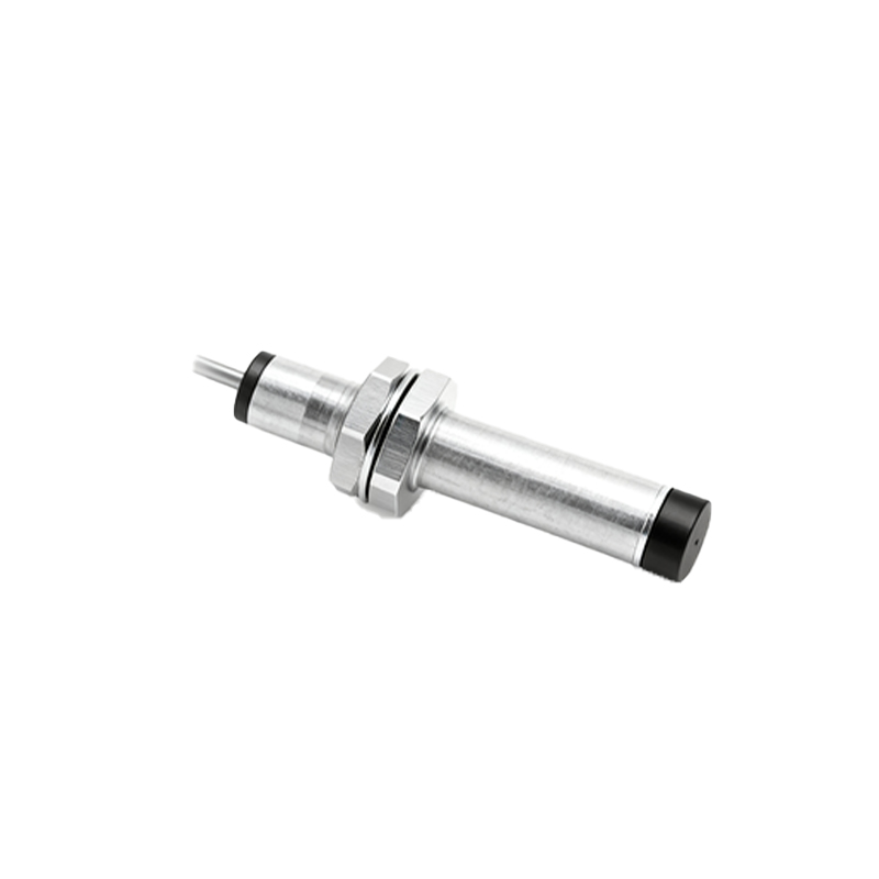
1. Power Source Connection: Identify your DC power supply. The most common voltage is 24V DC, but always confirm it is within your sensor's rated range. The power supply should be adequately sized to handle the combined current draw of the sensor and the load.
2. Sensor Terminal Identification: A two-wire sensor has only two connecting wires or terminals. They are typically color-coded: Brown (or sometimes Black) for the positive (+) lead and Blue for the negative (-) lead. This follows the international IEC standard (IEC 60947-5-2). Always consult the sensor's manual, as some manufacturers may use different colors.
3. Circuit Configuration - Series Connection: The fundamental rule is that the sensor, the load, and the power supply are connected in series. There is no separate common or ground wire for the load.
Connect the Brown wire from the sensor to the positive (+) terminal of your DC power supply.
Connect the Blue wire from the sensor to one terminal of your load (e.g., terminal A1 of a relay coil, or the positive terminal of a PLC digital input module).
Connect the other terminal of your load back to the negative (-) terminal of the DC power supply.
This completes the series loop: Power (+) -> Sensor -> Load -> Power (-).
4. Load Considerations: The load is a critical factor. A two-wire sensor requires a minimum load current (often 2-5mA) to operate correctly. If the connected load (like a high-impedance PLC input) draws less than this minimum, the sensor may not switch reliably or may exhibit chatter. Conversely, you must never exceed the sensor's maximum switching current. If your load requires more current, you must use an intermediate relay. The sensor switches the relay coil, and the relay's contacts, rated for higher current, then control the primary load.
5. Protective Devices: It is highly recommended to include a fast-blow fuse (rated just above the total circuit current) in the positive line to protect against short circuits. For inductive loads like relay coils, a flyback diode or a surge suppressor (RC network or metal-oxide varistor) should be installed in parallel with the load to suppress voltage spikes that can damage the sensor's solid-state switching element.
6. Testing and Verification: After wiring, perform a careful visual inspection. Apply power. Use a non-ferrous (for capacitive) or ferrous (for inductive) target to actuate the sensor. Verify the load energizes correctly. Use a multimeter to check the voltage drop across the sensor in both the on and off states. A significant drop when on (e.g., 2-5V) is normal due to its internal resistance.
Common Troubleshooting Issues:
Sensor does not switch: Check for wiring errors (not in series), insufficient voltage,